A bag filter dust removal device

A bag-type dust collector and ash cleaning device technology, applied in chemical instruments and methods, separation methods, climate sustainability, etc., can solve the problems of increased investment cost, insufficient space layout, and many blowing pipes, etc., and increase the dust removal area. , The effect of reducing equipment investment and prolonging service life

Active Publication Date: 2022-04-05
SHANDONG MICROGRAM ENVIRONMENTAL PROTECTION TECH CO LTD
View PDF3 Cites 0 Cited by
  • Summary
  • Abstract
  • Description
  • Claims
  • Application Information

AI Technical Summary

Problems solved by technology

[0004] The disadvantage of line injection is that there are many injection pipes and pulse valves, it is inconvenient to replace the filter bag, and the space arrangement is not enough to use low-pressure and high-flow injection pipes
[0005] Disadvantages of rotary blowing: On the one hand, because the nozzles at different radius positions on the rotary arm have different rotation strokes at the same time, the distance between the centers of the filter bags arranged on different radii on the perimeter is the same
However, due to the short pulse injection time, there is always negative pressure in the box. After the pulse injection, the dust that has just been blown off is easily affected by the negative pressure and returns to the bag, forming the so-called secondary bag in the industry. Secondary dusting, secondary dusting will reduce the effect of blowing dust cleaning, and cannot achieve high-efficiency bag body cleaning
At present, the whole box off-line method is often used in the industry to solve the secondary dust problem, but this method will add an extra box, which not only increases the floor area of ​​the dust collector, but also increases the investment cost.

Method used


Image

  • A bag filter dust removal device
  • A bag filter dust removal device
  • A bag filter dust removal device

Examples


Embodiment 1

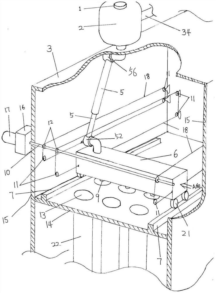
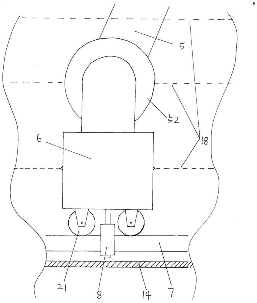
[0107] Such as figure 1 As shown, the side plate 15 of the clean air chamber, the flower plate 14, and the top plate 3 of the clean air chamber jointly constitute the clean air chamber of the bag filter. Outside the top surface of the clean air chamber and fixed on the top plate 3 of the clean air chamber and its structural beams, an air bag 2 is provided, which is connected to the Roots blower through the air bag inlet pipe 34 . The gas bag 2 is equipped with a pulse valve 1, and the pipeline connected to the outlet of the pulse valve 1 passes through the top plate 3 and enters the clean gas chamber to become horizontal, and connects the swivel joint 56 in the horizontal section, and then connects the gas delivery pipe 5. Air pipe 5 is the telescoping tube that is moved and matched suit by big and small two section tubes. The lower casing of the air pipe is connected to a rotary joint 52, which is connected to the end of the blowing pipe 6. The bottom of the blowing pipe 6 ...

Embodiment 2

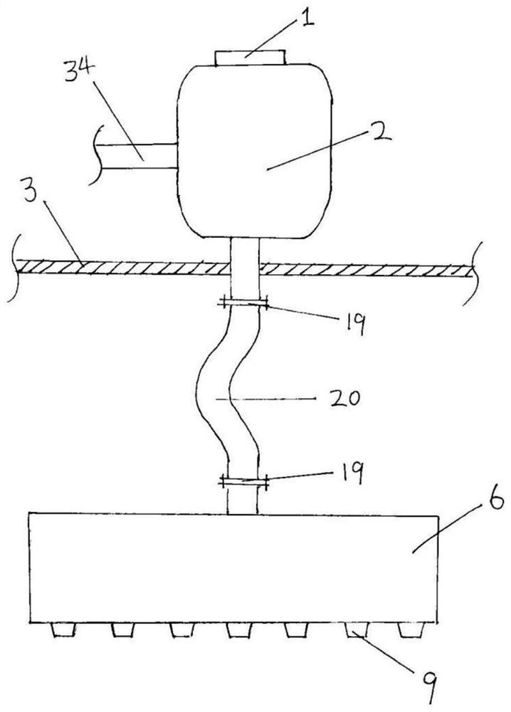
[0113] Such as figure 2 As shown, the difference from Embodiment 1 is that the pipeline connected to the outlet of the pulse valve 1 passes through the top plate 3 and enters the clean air chamber, and then connects with the flange 19 at one end of the flexible gas transportation hose 20 . The other flange 19 of the gas delivery hose 20 is connected to the end of the blowing pipe 6, and the pulse gas is introduced into the blowing pipe 6 and sprayed into the quasi-elliptical filter bag mouth 23 through the nozzle 9 to remove the filter bag 22. Dust accumulation on exterior surfaces.

[0114] Another difference from Embodiment 1 is that, as Figure 17 As shown, a brake line working end is provided above the pocket cover supporting plate 25, and the working end drives a lever-type mechanism 33 for relying on the steel wire of the brake line core, and the lever mechanism relies on spring force to keep the Fixed posture. When operating the operating end of the brake wire 28, t...

Embodiment 3

[0117] exist figure 1 Basically, the blowing pipe is also provided with a wind blocking baffle.

[0118] Figure 4 It is a schematic diagram of one side of the connection between the wind blocking cover plate 35 and the blowing pipe 6 , and the connection relationship on the other side is consistent with the connection relationship on this side.

[0119] Such as Figure 4 As shown, the wind blocking cover plate 35 is provided with a lifting guide rail 36, and the blowing pipe 6 is provided with a cover plate lifting guide wheel 37, and the lifting guide rail 36 moves up and down outside the cover plate lifting guide wheel 37, and the lifting guide rail 36 and the cover plate lifting guide wheel The connecting device that wheel 37 forms connects wind-blocking cover plate 35 with blowing pipe 6 . Both sides of the wind-blocking cover plate 35 are provided with lifting rollers 45, and the lifting rollers 45 are on the wind-blocking cover plate track 46 (see Figure 5 ), the ...


PUM


Abstract

A dust removal device for a bag type dust collector, which is provided with a moving blowing pipe device, and is used for pulse ejection of blowback gas for dust removal, and the blowing pipe (6) with a nozzle (9) moves back and forth in a straight line to blow the filter at different positions. The bag (22), the air pipe (5) between the air bag (2) and the blowing pipe (6) is non-displaceable near the end of the air bag pulse valve (1), and the end near the blowing pipe (6) is with the blowing pipe (6). blowpipe displacement.

Description

technical field [0001] The invention relates to a dust cleaning device for a bag type dust collector, which belongs to the field of environmental protection dust control. Background technique [0002] A complete main body of the bag filter, taking the mainstream vertical external filter dust collector as an example, there are dust hoppers, filter chambers, air inlet passages connected to it on one side of the filter chamber and possible valves from bottom to top , the clean air chamber and the air outlet channel connected with the clean air chamber and the possible valves. The ash hopper is used to store the dust and regularly discharge the ash through the ash discharge valve on the ash hopper. There are a large number of cylindrical filter bags made of filter materials in the filter chamber, and the filter bags are hung on the flower board. The flower plate is also called a porous plate, which refers to a steel plate with holes for installing filter bags, which isolates t...

Claims


Application Information

Patent Timeline
Patent Type & Authority Patents(China)
IPC IPC(8): B01D46/02B01D46/04B01D46/682
CPCB01D46/023B01D46/04B01D46/446B01D46/46B01D46/00B01D46/02
Inventor 姚航东佃军姚朝胜刘建国贾凯迪
Owner SHANDONG MICROGRAM ENVIRONMENTAL PROTECTION TECH CO LTD
Why Eureka
Try Eureka