A textile fabric dust removal equipment

A technology for dust removal equipment and fabrics, used in textiles and papermaking, liquid/gas/vapor removal by jet method, mechanical cleaning, etc. simple structure

Active Publication Date: 2018-03-16
GUANGDONG YI SEN CARPET CONSULTANTS
View PDF5 Cites 0 Cited by
  • Summary
  • Abstract
  • Description
  • Claims
  • Application Information

AI Technical Summary

Problems solved by technology

[0002] At present, in the daily production of textiles, it is necessary to remove dust from the fabric. The common way of dust removal is that the operator holds a hand spray gun to remove dust from the fabric, which is not only labor-intensive, but also has a poor dust removal effect.

Method used


Image

  • A textile fabric dust removal equipment

Examples


Embodiment Construction

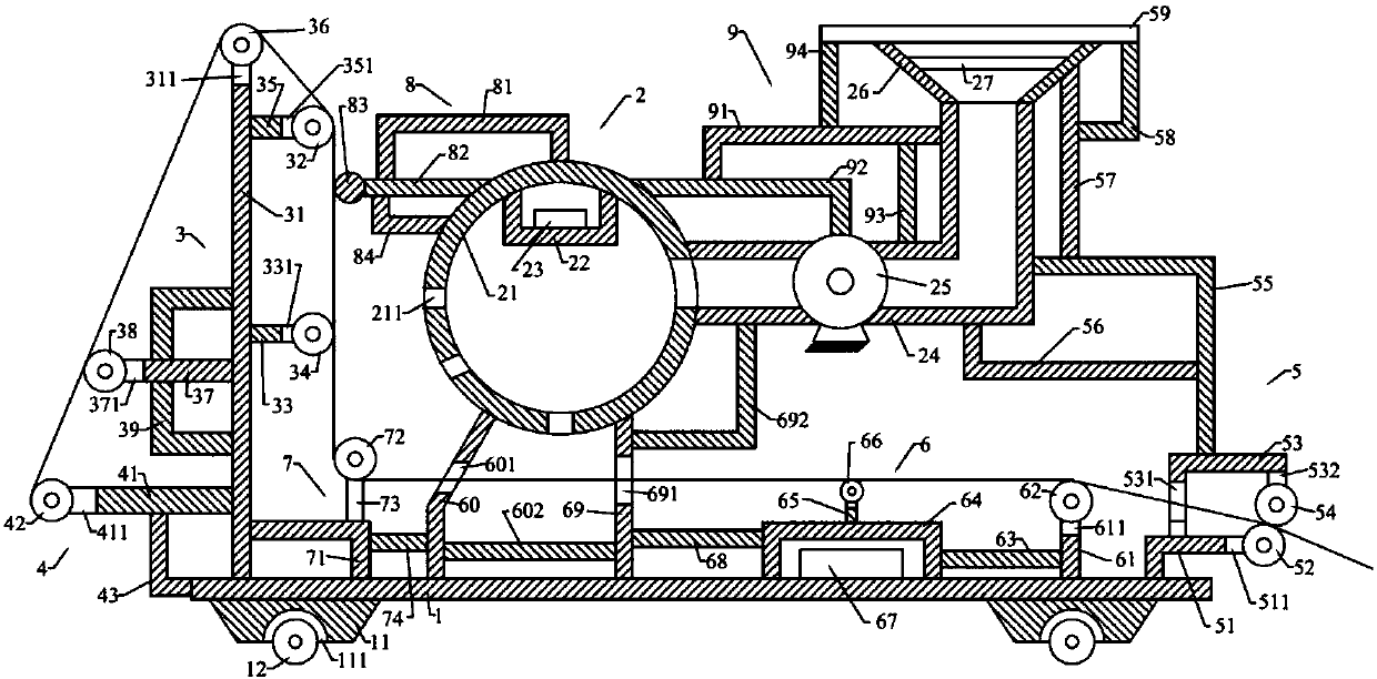
[0020] like figure 1 As shown, the textile fabric dust removal equipment of the present invention includes a base plate 1, an air blowing device 2 positioned above the base plate 1, a support device 3 positioned on the left side of the blowing device 2, and a winding device located below the support device 3. Device 4, the pressing device 5 on the right side of the support device 3, the support device 6 above the bottom plate 1, the roller device 7 on the left side of the support device 6, the blower device 2 above the The abutting device 8 and the fixing device 9 located on the right side of the blowing device 2 .

[0021] like figure 1 As shown, the base plate 1 is a cuboid, and the base plate 1 is placed horizontally. The base plate 1 is provided with a first support block 11 below it and a first roller 12 below the first support block 11. The first support block 11 is provided with two and is respectively located on the left and right sides below the bottom plate 1. The ...


PUM


Abstract

The invention relates to fabric dust removing equipment for a textile industry. The equipment is composed of a base plate, a blowing device, a bracket device, a rolling device, a pressing device, a supporting device, a roller device, an abutting device and a fixing device. A first support block and a first roller are arranged on the base plate. The blowing device consists of a blowing frame, a first radiating frame, a first heating rod, an air inlet pipe, an air blower, an air inlet hopper and a first filter net. The bracket device includes a first support bar, a first cross bar, a second cross bar, a second roller, a third roller, a fourth roller, a third cross bar, a fifth roller and a first bracket. The rolling device includes a fourth cross bar, a sixth roller and a second bracket. The pressing device consists of a third bracket, a seventh roller, a fourth bracket, an eighth roller, a seventh bracket, a fifth bracket, a first vertical rod, a sixth bracket and a second filter net. And the supporting device includes a second vertical rod, a first rotating shaft, and a fourth vertical rod. According to the invention, the dust on the fabric can be removed completely. The dust removing equipment has the drying function; and a damp phenomenon of the fabric is prevented.

Description

technical field [0001] The invention relates to the technical field of textile machinery, in particular to a textile fabric dust removal device. Background technique [0002] At present, in the daily production of textiles, fabrics need to be dedusted. The common way of dedusting is that the operator holds a hand spray gun to dedust the fabrics, which is not only labor-intensive, but also has a poor dedusting effect. [0003] Therefore, it is necessary to provide a new technical solution to solve the above technical problems. Contents of the invention [0004] The object of the present invention is to provide a textile fabric dust removal equipment that can effectively solve the above technical problems. [0005] In order to solve the above technical problems, the present invention adopts the following technical solutions: [0006] A fabric dedusting device for textiles, the dedusting device for textile fabrics comprises a base plate, an air blowing device located above ...

Claims


Application Information

Patent Timeline
Patent Type & Authority Patents(China)
IPC IPC(8): D06G1/00D06B15/09
CPCD06B15/09D06G1/00
Inventor 邓小旺
Owner GUANGDONG YI SEN CARPET CONSULTANTS
Why Eureka
Try Eureka