
Control valve group, scattering hydraulic control system and rescue vehicle

A technology for controlling valves and control chambers, applied in the field of rescue, can solve problems such as the difficulty in realizing individual actions and speed control of operating units, and achieve the effect of reducing energy loss in the system

Active Publication Date: 2020-08-18
JIANGSU XCMG CONSTR MASCH RES INST LTD
View PDF15 Cites 0 Cited by
  • Summary
  • Abstract
  • Description
  • Claims
  • Application Information

AI Technical Summary

Problems solved by technology

However, it is difficult for the control valve group in the related art to realize the individual action and speed control of each working unit.

Method used


Image

  • Control valve group, scattering hydraulic control system and rescue vehicle
  • Control valve group, scattering hydraulic control system and rescue vehicle
  • Control valve group, scattering hydraulic control system and rescue vehicle

Examples


Embodiment Construction

[0046] Various exemplary embodiments of the present disclosure will now be described in detail with reference to the accompanying drawings. The description of the exemplary embodiments is illustrative only, and in no way restricts the disclosure, its application or uses. The present disclosure can be implemented in many different forms and is not limited to the embodiments described here. Rather, these embodiments are provided so that this disclosure will be thorough and complete, and will fully convey the scope of the disclosure to those skilled in the art. It should be noted that relative arrangements of parts and steps, compositions of materials, numerical expressions and numerical values ​​set forth in these embodiments should be interpreted as illustrative only and not as limiting, unless specifically stated otherwise.

[0047] "First", "second" and similar words used in the present disclosure do not indicate any order, quantity or importance, but are only used to distin...


PUM


Abstract

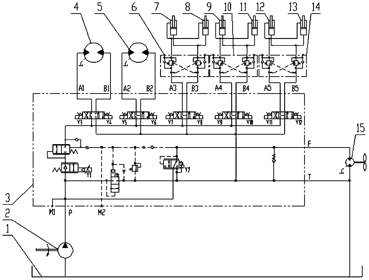
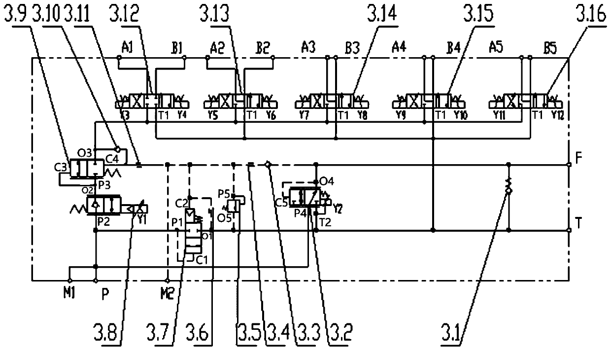
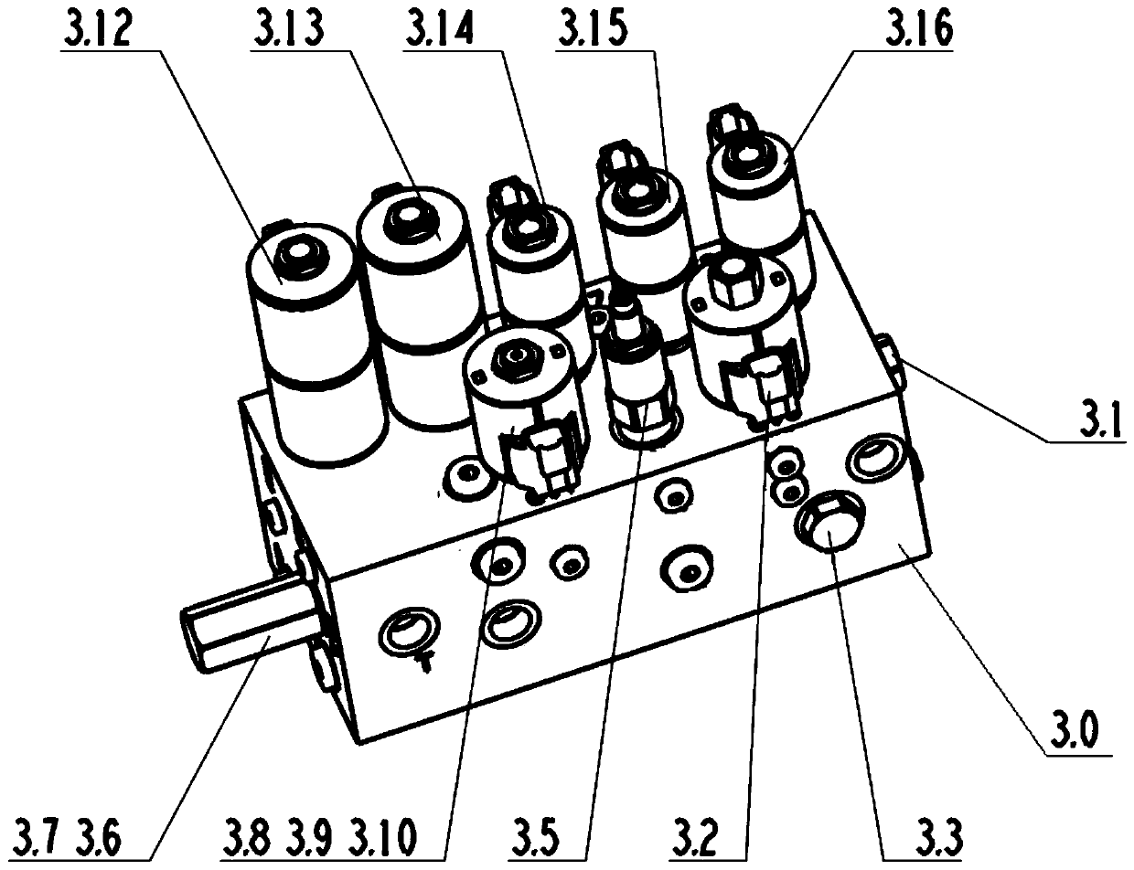
The invention relates to a control valve group, a scattering hydraulic control system and a rescue vehicle. The control valve group comprises a pilot logic valve (3.7), an electro-hydraulic proportional valve (3.8), a hydraulic logic valve (3.9) and at least two reversing valves. An oil inlet of each reversing valve communicates with one of a first control chamber (C1) and a second control chamber(C2) to control opening and closing of an oil channel of a first oil inlet (P1) and a first oil outlet (O1) inside the pilot logic valve (3.7); and the electro-hydraulic proportional valve (3.8) is arranged to independently control pressure oil flow of a working oil circuit of a working unit corresponding to each of the at least two reversing valves according to a received first control current.The embodiment can achieve individual action and speed control of a plurality of work units.

Description

technical field [0001] The present disclosure relates to the field of rescue, in particular to a control valve group, a hydraulic control system for spreading and a rescue vehicle. Background technique [0002] With the demand for fire extinguishing by sand throwing in the rescue process, some sand throwing fire extinguishing trains with mechanization, high degree of automation and strong maneuverability have been developed or produced in related technologies. For the sand throwing fire extinguishing vehicle, it includes a plurality of operating units, such as drum throwing rotating motor, impeller shell rotating motor, adjusting head oil cylinder, feeding adjusting oil cylinder, ejecting drum adjusting oil cylinder, etc. However, it is difficult for the control valve group in the related art to realize the individual action and speed control of each working unit. Contents of the invention [0003] In view of this, the embodiments of the present disclosure provide a contr...

Claims


Application Information

Patent Timeline
Patent Type & Authority Applications(China)
IPC IPC(8): F15B13/06F15B11/16F15B11/042
CPCF15B13/06F15B11/16F15B11/042F15B2211/20538F15B2211/41572F15B2211/45
Inventor 杜辰蕊汉京勇王川川
Owner JIANGSU XCMG CONSTR MASCH RES INST LTD
Learn More