Automatic pressurizing low-temperature liquid delivery method and device

A low-temperature liquid, self-pressurizing technology, applied in boiling devices, evaporation devices, chemical instruments and methods, etc., can solve the problems of low-temperature liquid cannot be sent normally, low-temperature liquid cannot be sent, booster pump cannot be turned on, etc., to save equipment. The effect of investment, avoiding liquid loss and saving delivery time

Inactive Publication Date: 2020-08-18
开封黄河空分集团有限公司
View PDF7 Cites 2 Cited by
  • Summary
  • Abstract
  • Description
  • Claims
  • Application Information

AI Technical Summary

Problems solved by technology

[0004] In the traditional cryogenic liquid sending process, when the pressure of the graduated cylinder is lower than the storage tank pressure, the cryogenic liquid cannot be sent to the storage tank normally. To solve this problem, it is necessary to pressurize the cryogenic liquid
[0005] In the existing low-temperature liquid pressurization method, a booster pump is usually installed on the liquid outlet pipe between the measuring cylinder and the storage tank to realize the delivery of the low-temperature liquid; The operation can only be started at the corresponding temperature, which will inevitably cause a large amount of gasification of the cryogenic liquid, resulting in too much energy loss. Due to the limited space in the air separation cold storage box, the capacity of the measuring cylinder is not large, especially when the amount of cryogenic liquid sent is also small. , the liquid in the measuring cylinder has been completely vaporized, the booster pump has not yet reached its starting temperature, the booster pump cannot be turned on, and the low-temperature liquid cannot be sent out

Method used


Image

  • Automatic pressurizing low-temperature liquid delivery method and device
  • Automatic pressurizing low-temperature liquid delivery method and device
  • Automatic pressurizing low-temperature liquid delivery method and device

Examples


Embodiment Construction

[0030] The technical solutions of the present invention will be clearly and completely described below in conjunction with the accompanying drawings. Apparently, the described embodiments are some of the embodiments of the present invention, but not all of them. Based on the embodiments of the present invention, all other embodiments obtained by persons of ordinary skill in the art without making creative efforts belong to the protection scope of the present invention.

[0031] In the description of the present invention, it should be noted that the terms "first", "second", and "third" are used for description purposes only, and should not be understood as indicating or implying relative importance.

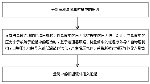
[0032] Such as figure 1 As shown, the automatic pressurized cryogenic liquid delivery method of the present invention comprises the following steps:

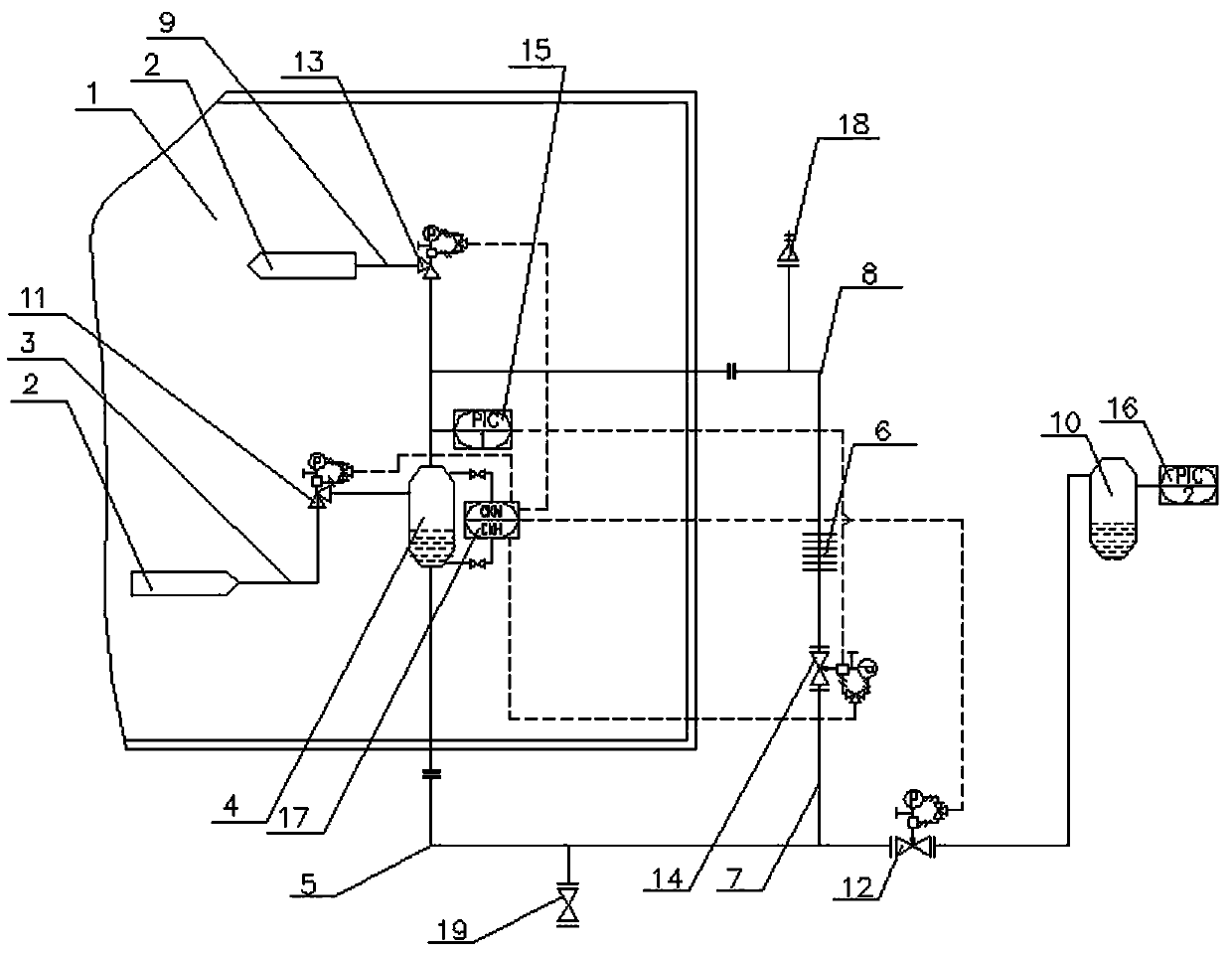
[0033] Step 1: obtain the pressure in the measuring cylinder 4 and the storage tank 10 respectively;

[0034] Step 2: a self-pr...


PUM


Abstract

The invention discloses an automatic pressurizing low-temperature liquid delivery method and device. A self pressurizing mechanism communicating with a measuring cylinder is mounted, pressure in the measuring cylinder and pressure in a storage groove are compared, when the pressure in the measuring cylinder is smaller than or equal to the pressure in the storage groove, based on a communicator principle, the low-temperature liquid in the measuring cylinder is guided into the self pressurizing mechanism, the self pressurizing mechanism liquefies and evaporates the guided-in low-temperature liquid, pressurizing gas is generated, the pressurizing gas is guided into the measuring cylinder, the pressure in the measuring cylinder can be improved, and liquid in the measuring cylinder can be smoothly fed into the storage groove.

Description

technical field [0001] The invention relates to the technical field of air separation, in particular to a method and device for sending out low-temperature liquid with automatic pressurization. Background technique [0002] At present, with the development of social economy, in recent years, the application fields of air separation equipment have been continuously expanded, such as petrochemical, glass, rubber, construction, carbon fiber and other industries. Enterprises have continuously improved requirements for air separation equipment, and put forward higher requirements for the stability and operability of air separation systems. [0003] Sending out the cryogenic liquid refers to sending the cryogenic liquid in the distillation tower to the measuring cylinder, the measuring cylinder is located in the cold storage box, and the liquid in the measuring cylinder is sent to the storage tank. [0004] In the traditional cryogenic liquid sending process, when the pressure of...

Claims


Application Information

Patent Timeline
Patent Type & Authority Applications(China)
IPC IPC(8): F17D1/08F17D1/02F17D3/01F15B3/00B01B1/00
CPCB01B1/005F15B3/00F17D1/02F17D1/082F17D3/01
Inventor 孙记章谷春征黄动雷
Owner 开封黄河空分集团有限公司
Why Eureka
Try Eureka