Waste liquid incineration equipment for pesticide production

A waste liquid and pesticide technology, which is applied in lighting and heating equipment, incinerators, combustion methods, etc., can solve the problems of incomplete treatment of high-concentration pesticide waste liquid and the need to improve environmental protection

Inactive Publication Date: 2020-08-18
ANHUI YINONG CHEM
View PDF7 Cites 0 Cited by
  • Summary
  • Abstract
  • Description
  • Claims
  • Application Information

AI Technical Summary

Problems solved by technology

However, the incinerator is incomplete for the treatment of high-concentration

Method used


Image

  • Waste liquid incineration equipment for pesticide production
  • Waste liquid incineration equipment for pesticide production
  • Waste liquid incineration equipment for pesticide production

Examples


Embodiment 1

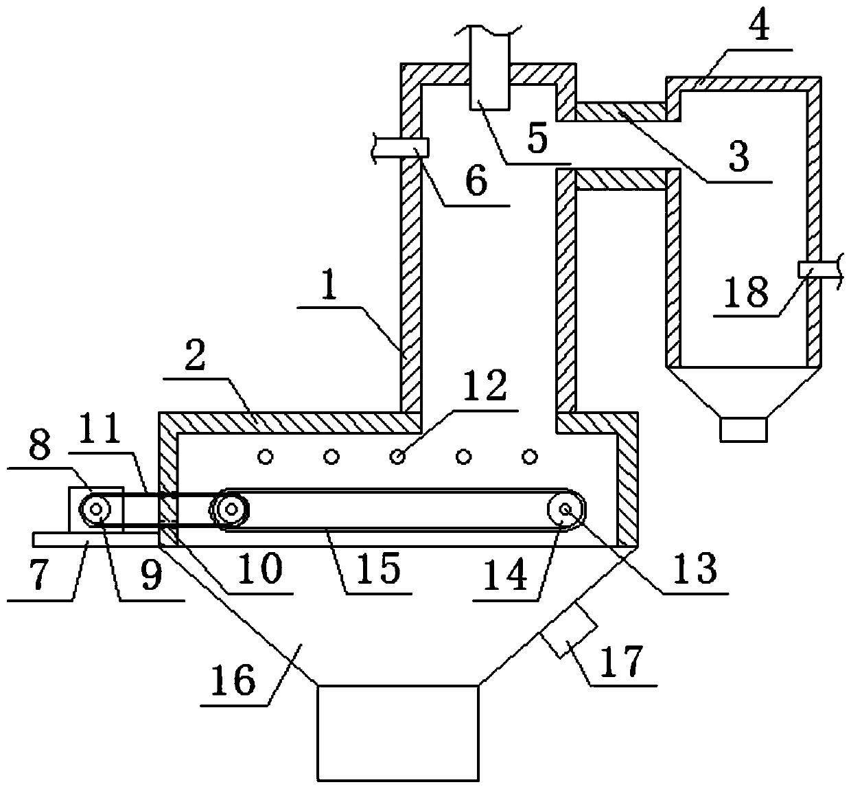
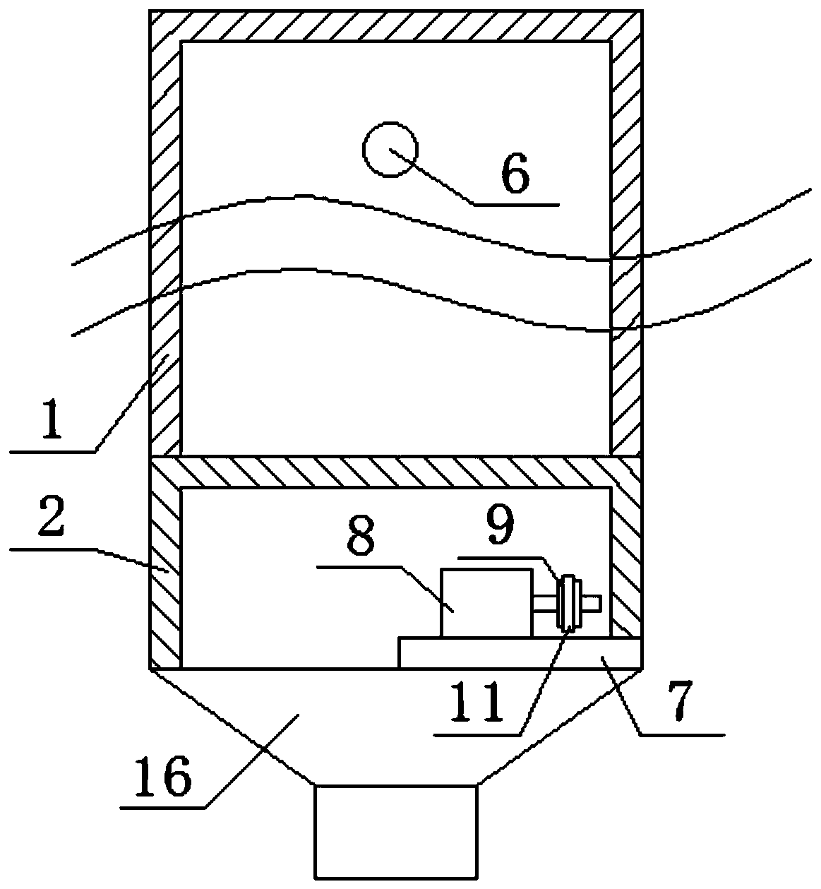
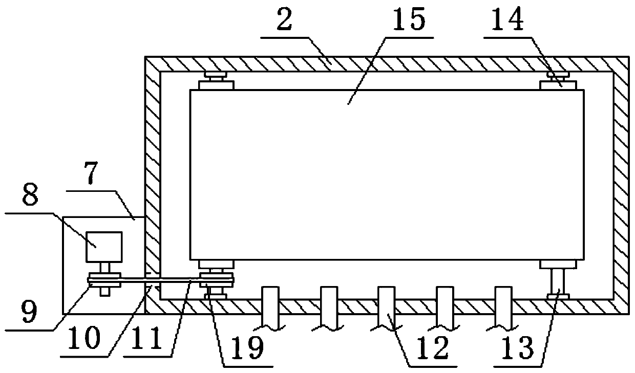
[0021] refer to Figure 1-3 , a waste liquid incineration device for pesticide production, comprising a first combustion chamber 1, a second combustion chamber 2 is fixedly installed on the bottom of the first combustion chamber 1, and a channel 3 is fixedly installed on one side of the first combustion chamber 1 One end, the other end of the passage 3 is fixedly installed with an auxiliary combustion chamber 4, the top center of the first combustion chamber 1 is fixedly installed with a first burner 5, and the side of the first combustion chamber 1 away from the passage 3 is fixedly installed with a high-pressure nozzle 6 , and both the first burner 5 and the high-pressure nozzle 6 extend into the first combustion chamber 1, the bottom of one side of the second combustion chamber 2 is fixedly installed with a support plate 7, and the top of the support plate 7 is fixedly installed with a motor 8. 8 is fixedly sleeved with a drive wheel 9 on the output shaft of 8, and the seco...

Embodiment 2

[0027] refer to Figure 1-3 , a waste liquid incineration device for pesticide production, comprising a first combustion chamber 1, a second combustion chamber 2 is fixedly installed on the bottom of the first combustion chamber 1, and a channel 3 is fixedly installed on one side of the first combustion chamber 1 One end, the other end of the passage 3 is fixedly installed with an auxiliary combustion chamber 4, the top center of the first combustion chamber 1 is fixedly installed with a first burner 5, and the side of the first combustion chamber 1 away from the passage 3 is fixedly installed with a high-pressure nozzle 6 , and both the first burner 5 and the high-pressure nozzle 6 extend into the first combustion chamber 1, the bottom of one side of the second combustion chamber 2 is fixedly installed with a support plate 7, and the top of the support plate 7 is fixedly installed with a motor 8. 8 is fixedly sleeved with a drive wheel 9 on the output shaft of 8, and the seco...


PUM


Abstract

The invention belongs to the technical field of incineration equipment, particularly relates to waste liquid incineration equipment for pesticide production. The following scheme for solving the problem of incomplete incineration in the prior art is provided, the waste liquid incineration equipment comprises a first combustion chamber, a second combustion chamber is fixedly mounted at the bottom of the first combustion chamber, one end of a channel is fixedly mounted on one side of the first combustion chamber, an auxiliary combustion chamber is fixedly installed at the other end of the channel, a first combustor is fixedly installed in the center of the top of the first combustion chamber, a high-pressure nozzle is fixedly installed on one side, away from the channel, of the first combustion chamber, the first combustor and the high-pressure nozzle extend into the first combustion chamber separately, and a supporting plate is fixedly installed at the bottom of one side of the second combustion chamber. The waste liquid incineration equipment for pesticide production is simple in structure, reasonable in design and convenient to operate, incineration disposal can be carried out onhigh-concentration pesticide waste liquid, the waste liquid disposal effect can be ensured, and the waste liquid incineration equipment is environmentally friendly and high in practicability.

Description

technical field [0001] The invention relates to the technical field of incineration equipment, in particular to a waste liquid incineration equipment for pesticide production. Background technique [0002] The wastewater produced in the production of pesticides is toxic and harmful industrial wastewater, with complex components, containing a large amount of organic matter with poor biodegradability and difficult to biodegrade, and has poor biodegradability, especially high-concentration organic pesticide wastewater (such as distillation concentrate). The impact of the biological treatment system is relatively large, which often causes a large number of microorganisms to die. After the treatment, the effluent quality fluctuates greatly, and sometimes exceeds the standard, which brings great pressure to the environmental protection work of the enterprise. Waste liquid is a product that must be treated in industrial production. There are various ways to deal with it. [0003] ...

Claims


Application Information

Patent Timeline
IPC IPC(8): F23G7/04F23G5/16F23G5/44F23G7/06F23J1/00
CPCF23G7/04F23G5/16F23G5/446F23G7/06F23J1/00F23G2209/101
Inventor 徐益峰吴兵方润徐金娇刘明浩赵辉张静宁早霞潘微微
Owner ANHUI YINONG CHEM
Why Eureka
Try Eureka