Self-energy type thermal response monitoring device

A monitoring device and thermal response technology, which is applied in the field of self-energy thermal response monitoring device, can solve problems such as thermal monitoring blank period

Active Publication Date: 2020-08-18
ZHEJIANG UNIV
View PDF5 Cites 7 Cited by
  • Summary
  • Abstract
  • Description
  • Claims
  • Application Information

AI Technical Summary

Problems solved by technology

[0004] At present, most thermal sensors need to be installed with batteries or connected to an external power source, so there will be a thermal monitoring blank period when the battery is replaced or the power is unexpectedly cut off.

Method used


Image

  • Self-energy type thermal response monitoring device
  • Self-energy type thermal response monitoring device
  • Self-energy type thermal response monitoring device

Examples


Embodiment Construction

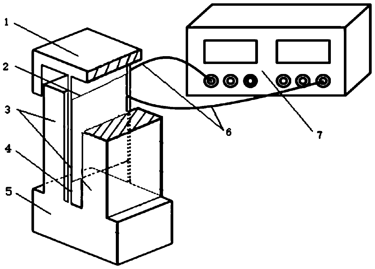
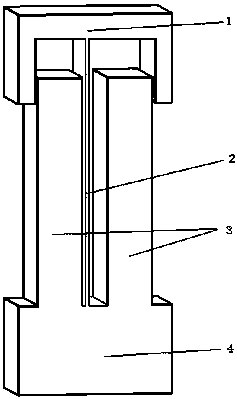
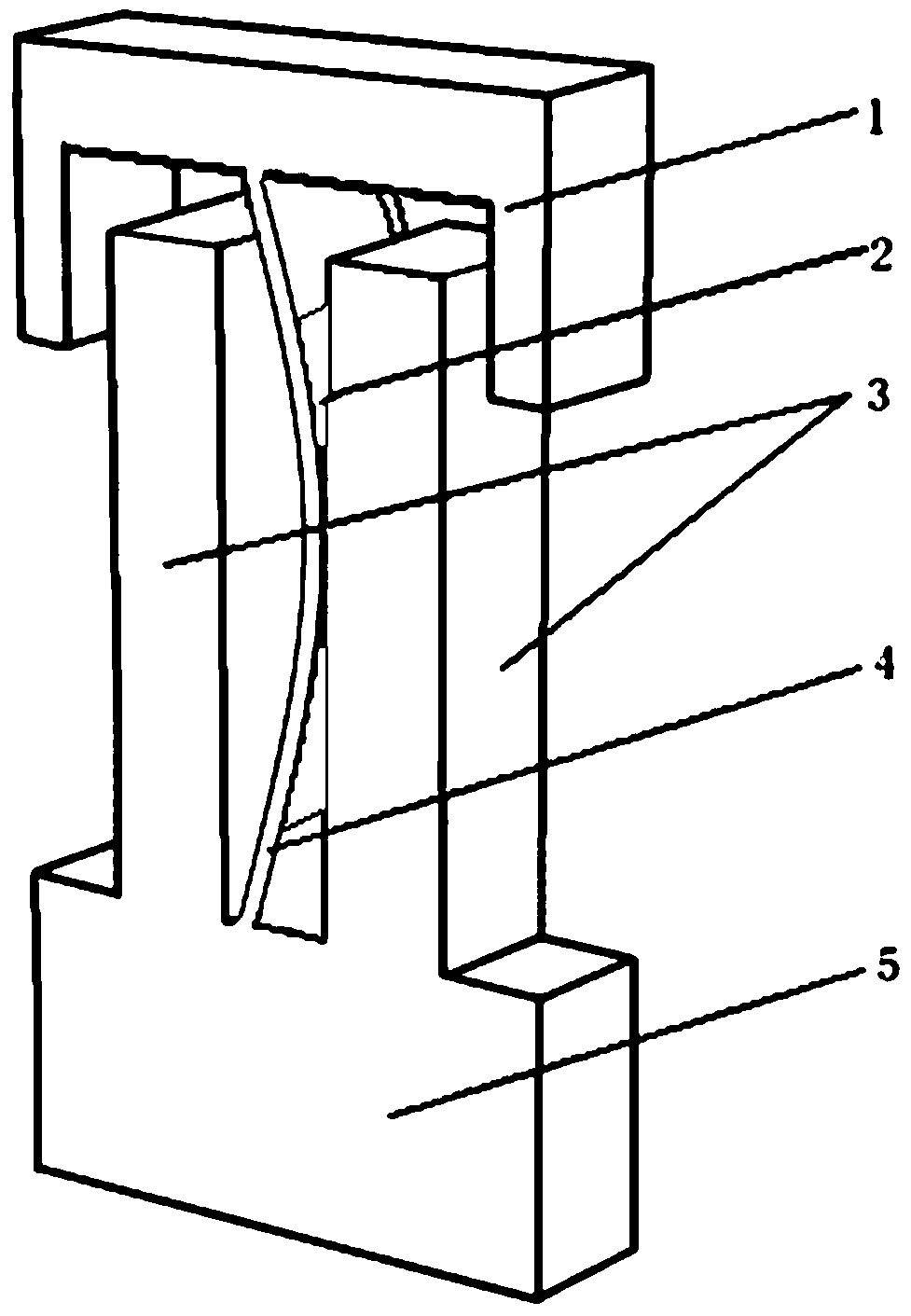
[0021] As shown in the figure, a self-energy type thermal response monitoring device includes a surrounding constraint component, a frequency conversion beam 4 arranged in the surrounding constraint component, a piezoelectric patch 2 covered on the frequency conversion beam 4, and a piezoelectric patch 2 electrical signal collectors 7 electrically connected.

[0022] As an optimized structure of the present invention: the surrounding restraint assembly includes a lower support 5, side restraints 3 fixedly connected to both sides of the lower support 5, an upper support 1 movably arranged at the upper ends of the two side restraints 3, and a frequency conversion beam 4 Located in the accommodating space enclosed by the lower support 5 , the lower support 5 and the side constraint 3 , the upper and lower ends of the frequency conversion beam 4 are fixedly connected to the upper support 1 respectively. Wherein, the side constraint 3 is not connected with the upper support 1 , and...


PUM


Abstract

The invention belongs to the field of structural health monitoring, and particularly relates to a self-energy type thermal response monitoring device which comprises a peripheral constraint assembly,a frequency conversion beam arranged in the peripheral constraint assembly, a piezoelectric patch covering the frequency conversion beam and an electric signal collector electrically connected with the piezoelectric patch. According to the invention, the deformation of the variable-frequency beam is limited by innovatively using rigid constraint, and a low-frequency thermal load is converted intoa high-frequency post-buckling impact to trigger the piezoelectric material to generate an electric signal. According to the invention, a mode of triggering an electric signal by specific displacementis innovatively used; characteristics of the frequency conversion beam and the piezoelectric material are creatively combined and utilized, energy conversion from environmental heat energy to mechanical energy to electric energy is achieved, and therefore the thermal response monitoring equipment can achieve electric energy self-supply and can also supply electric energy to other external equipment at the same time.

Description

technical field [0001] The invention belongs to the fields of structural health monitoring and energy collection, and in particular relates to a self-energy thermal response monitoring device. Background technique [0002] Thermal loads due to temperature fluctuations, such as thermal expansion and contraction cycles caused by diurnal or seasonal temperature changes, have a significant impact on the stability and durability of infrastructure. Therefore, thermal load is defined as one of the important limit states for structural bearings. To mitigate the effects of these thermal loads, the design of structural elements in civil infrastructure often takes thermal expansion and contraction into account. Fully considering the thermal effect of concrete structures requires measuring the temperature change of its structural members. However, without effective thermal detection, the effect of temperature fluctuations on the response of concrete structures cannot be accurately pre...

Claims


Application Information

Patent Timeline
Patent Type & Authority Applications(China)
IPC IPC(8): G01K5/58G01B7/16
CPCG01K5/58G01B7/16G01M5/0083
Inventor 焦鹏程候博之杨洁杨旸
Owner ZHEJIANG UNIV
Why Eureka
Try Eureka