Low speed impact position identification method based on approximate entropy calculation

A technology of low-speed impact and identification method, applied in impact testing, measurement devices, optical devices, etc., can solve the problems of low practicability, reduced Lamb wave accuracy, Lamb wave dispersion, etc.

Active Publication Date: 2017-03-08
NANJING UNIV OF AERONAUTICS & ASTRONAUTICS
View PDF5 Cites 11 Cited by
  • Summary
  • Abstract
  • Description
  • Claims
  • Application Information

AI Technical Summary

Problems solved by technology

[0003] At present, in the shock load location identification method based on the study of shock excitation of Lamb waves in the plate structure, triangular location, quadrilateral location, and time difference location based on wavelet transform are usually used, and good shock location identification results have been achieved. There are complex phenomena such as dispersion in the wave propagation process, which directly reduces the accuracy of positioning based on Lamb waves
In addition, impact location identification methods based on neural networks, support vector machines, etc. that require a large amount of prior knowledge require heavy work before positioning to obtain sample signals of each impact point, and then let the signal of the point to be measured be substituted into the trained classifier For pattern recognition, such methods are less practical

Method used


Image

  • Low speed impact position identification method based on approximate entropy calculation
  • Low speed impact position identification method based on approximate entropy calculation
  • Low speed impact position identification method based on approximate entropy calculation

Examples


Embodiment Construction

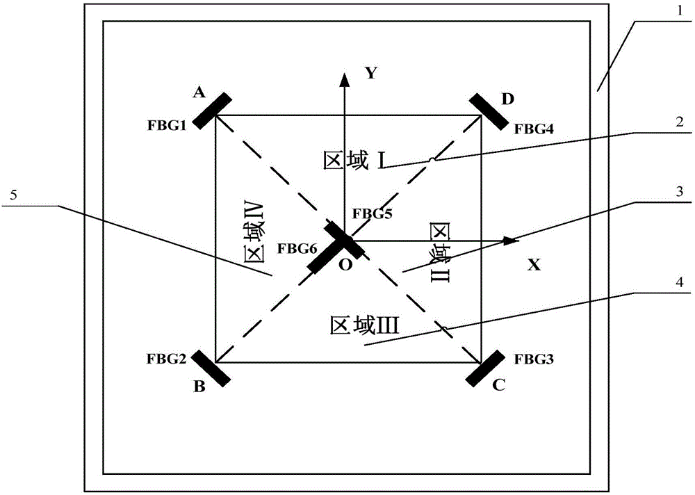
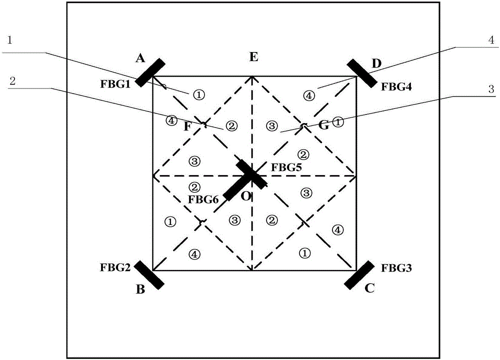
[0092] Step 1, distributed fiber Bragg grating sensor layout;

[0093] Select a square monitoring area ABCD at the center of the four-sided fixed support plate structure, where point A is located at the top left corner of the monitoring area, and A, B, C, and D are distributed in the counterclockwise direction at each vertex of the square monitoring area; select the plate structure to be monitored As the origin of the coordinates, establish a two-dimensional Cartesian coordinate system, define the X-axis parallel to the AD direction, and the Y-axis parallel to the AB direction; at the vertex positions A and C of the monitoring area, the axes are arranged parallel to the diagonal BD of the square monitoring area The Fiber Bragg Grating sensors are counted as FBG1 and FBG3 respectively, and the Fiber Bragg Grating sensors whose axes are parallel to the diagonal line AC of the square monitoring area are arranged at the apex positions B and D of the monitoring area, which are respe...


PUM


Abstract

The invention discloses a low speed impact position identification method based on approximate entropy calculation and belongs to the impact monitoring technology field of structure health monitoring. The method comprises the following steps of step1, carrying out distributed optical fiber bragg grating sensor layout; step2, adopting a calculating method of optical fiber bragg grating sensor impulse response signal approximate entropy; step3, collecting an optical fiber bragg grating sensor response signal corresponding to an impulse point to be measured and carrying out approximate entropy calculation; step4, determining an area where the point to be measured is located and calculating an approximation entropy of a sample impulse point response signal in the area; step5, constructing a relation model of a distance of the impulse point to a sensor and a corresponding approximation entropy difference value; and step6, based on a three-line crossing method, determining a position of the impulse point to be measured. A positioning algorithm in the invention possesses characteristics that a lot of prior knowledge is not needed; and practicality is high and so on.

Description

technical field [0001] The invention belongs to the technical field of impact monitoring for structural health monitoring, in particular to a plate structure impact monitoring method capable of quantitatively estimating the approximate entropy of signal complexity. Background technique [0002] It is difficult to monitor the low-speed impacts of bridge buildings, aerospace vehicles and other structures from falling parts, high-speed moving debris, flying birds in the air and ground vehicles. These low-speed impacts may cause damage that is difficult to observe from the outside with the naked eye. These damages are not noticeable, but slowly expand over time and can eventually be catastrophic. Therefore, timely low-speed impact monitoring is very necessary to provide early warning for potential dangers and remind relevant personnel to do maintenance work to ensure the safety and reliability of the structure. [0003] At present, in the shock load location identification meth...

Claims


Application Information

Patent Timeline
Patent Type & Authority Applications(China)
IPC IPC(8): G01B11/00G01M7/08
CPCG01B11/002G01M7/08
Inventor 曾捷喻俊松朱东方李志慧周煜青张益昕熊稚莉
Owner NANJING UNIV OF AERONAUTICS & ASTRONAUTICS
Why Eureka
Try Eureka