
Equipment base

A technology of equipment and base, applied in the field of equipment base, can solve the problems of uneconomical and environmental protection, poor construction convenience, non-adjustable, etc., and achieve the effect of reducing production cost, reducing self-weight, and reducing bearing capacity

Pending Publication Date: 2020-08-21
SHANGHAI MECHANIZED CONSTR GRP
View PDF0 Cites 0 Cited by
  • Summary
  • Abstract
  • Description
  • Claims
  • Application Information

AI Technical Summary

Problems solved by technology

[0004] The purpose of the present invention is to provide an equipment base, which can effectively solve the problems of poor construction convenience, non-adjustable and uneconomical and environmentally friendly monolithic concrete foundations in the prior art

Method used


Image

  • Equipment base
  • Equipment base
  • Equipment base

Examples


Embodiment

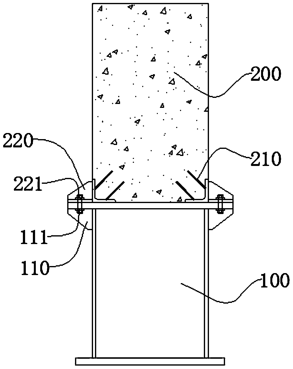
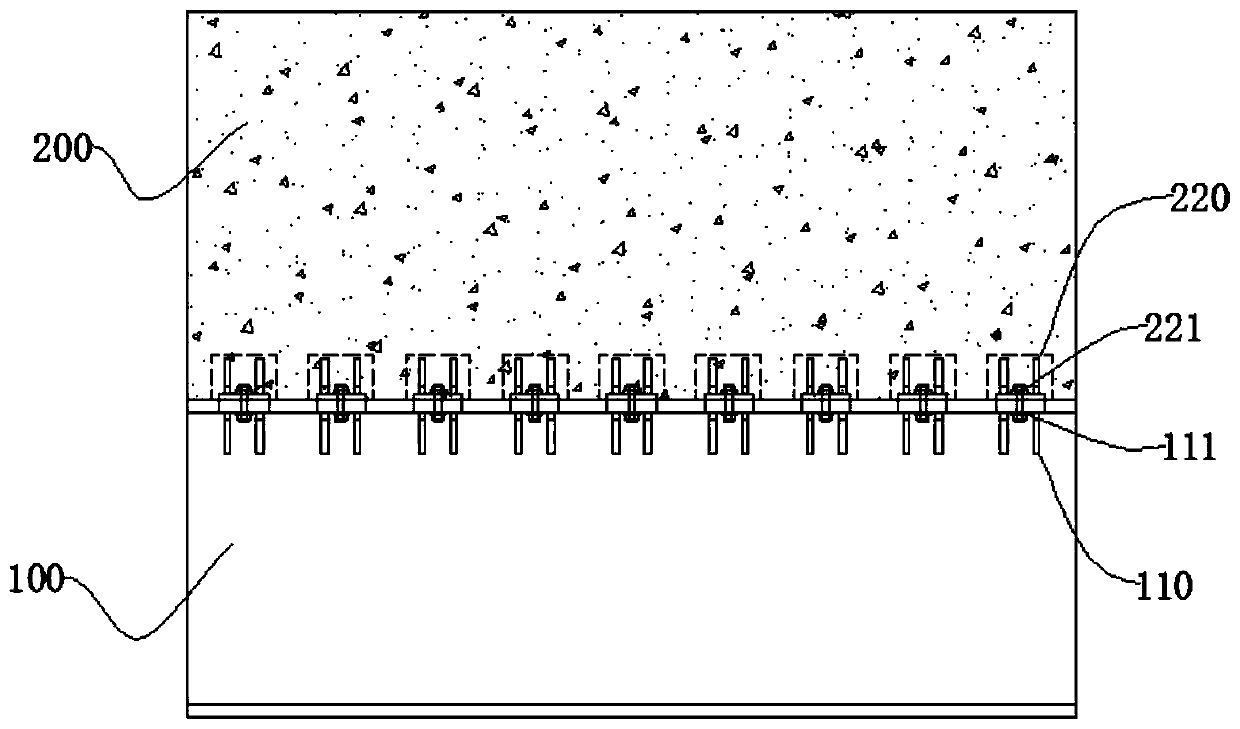
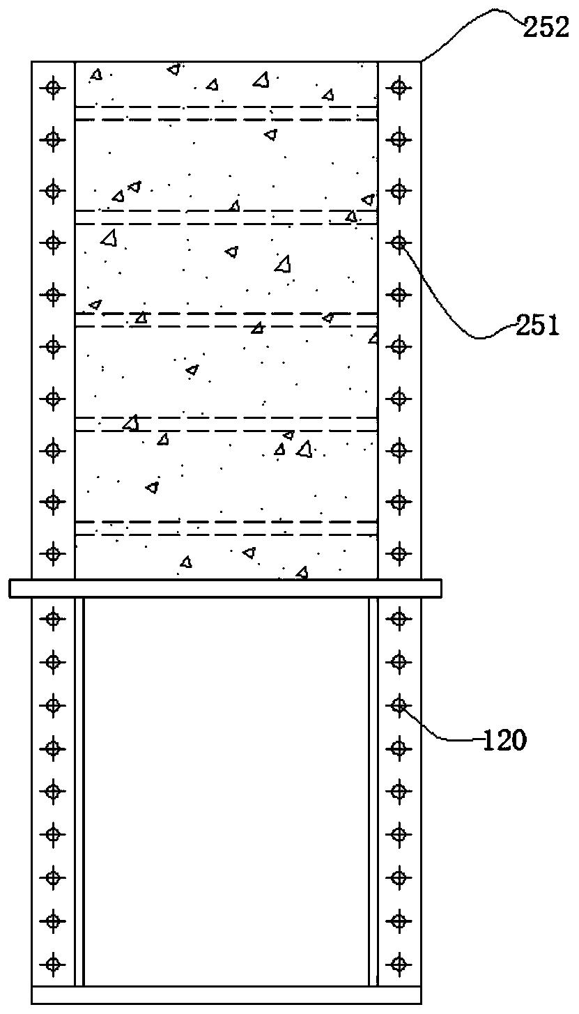
[0031] refer to Figure 1-8 , is a schematic diagram of the device base provided in this embodiment. refer to figure 1 A load-bearing base of the equipment base in this embodiment includes a steel main beam 100 and a prefabricated concrete beam 200, the precast concrete beam 200 is erected on the steel main beam 100, the side of the steel main beam 100 includes a first raised structure 110, the second A protruding structure 110 is provided with a first through hole 111, and the interior of the precast concrete beam 200 is provided with an embedded part 210, and also includes a second protruding structure 220, and the second protruding structure 220 is fixed on the internal embedded part 210, Moreover, a second through hole 221 is opened on the second protruding structure 220 .

[0032] During specific implementation, the prefabricated concrete beam 200 is erected on the steel main beam 100, the first through hole 110 is matched with the second through hole 220, and the bolt ...


PUM


Abstract

The invention discloses an equipment base. The equipment base is characterized by comprising at least one bearing unit, each bearing unit comprises a steel main beam and a precast concrete beam, the steel main beams comprise first protruding parts, the first protruding parts are fixed to the steel main beams, first through holes are formed in the first protruding parts, the precast concrete beamscomprise internal embedded parts and second protruding parts, the internal embedded parts are embedded in the precast concrete beams, the second protruding parts and the internal embedded parts are connected, and therefore the second protruding parts are fixed to the precast concrete beams. Second through holes are formed in the second protruding parts, when the precast concrete beams are erectedon the steel main beams, the first through holes and the second through holes are opposite, through bolts, connection is achieved, the precast concrete beams are fixed to the steel main beams, and thesteel main beams and the precast concrete beams are the same in extension direction. The equipment base is used for effectively solving the problems that in the prior art, a whole type concrete foundation is poor in construction convenience, adjusting is not carried out, and the foundation is not economical or environmentally friendly.

Description

technical field [0001] The invention relates to the field of mechanical manufacturing, in particular to an equipment base. Background technique [0002] The bases of existing gantry-type equipment often adopt different forms of integral concrete structures, and there are relevant design specifications for reference design. However, the construction period of cast-in-place concrete itself is long, and it takes a lot of manpower and material resources to set up the formwork and bind the steel bars. Therefore, the construction convenience of cast-in-place concrete is poor and the labor cost is high. Moreover, the cast-in-place concrete is formed as a whole after pouring, and it is not easy to move, recycle or adjust the form. Once the position of the processing and production workshop is adjusted, the site is relocated, the size of the equipment is changed, or the coverage of the equipment is adjusted, the original base is often only discarded. , Re-constructing a new base tha...

Claims


Application Information

Patent Timeline
Patent Type & Authority Applications(China)
IPC IPC(8): E02D27/44
CPCE02D27/44E02D2300/002E02D2300/0029E02D2600/20
Inventor 郑祥杰周锋陈晓明龚明武诣霖陆承麟周鸣李冀清
Owner SHANGHAI MECHANIZED CONSTR GRP
Learn More