Built-in corner plugin

A plug-in and corner technology, applied in the field of built-in corner plug-ins, can solve the problems of single structure of external joints, low construction efficiency, troublesome installation process, etc., achieve flexible quantity and fixed positions, improve construction efficiency and construction steps little effect

Pending Publication Date: 2020-08-21
郑州倍安科技有限公司
View PDF0 Cites 0 Cited by
  • Summary
  • Abstract
  • Description
  • Claims
  • Application Information

AI Technical Summary

Problems solved by technology

[0002] In the field of construction or industrial construction, frames are often used to support or set up work platforms. The frames are usually built from a large number of pipes. At present, the pipes of the frame are connected by welding, bolting or external joints. The installation process is cumbersome. There are many construction steps and the construction efficiency is not high
In addition, due to the relatively simple structure of the existing external joints, it is often only applicable to specific occasions, and the scope of application is relatively narrow

Method used


Image

  • Built-in corner plugin
  • Built-in corner plugin
  • Built-in corner plugin

Examples


Embodiment 1

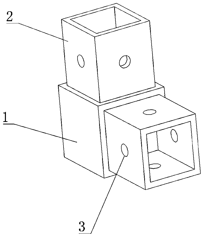
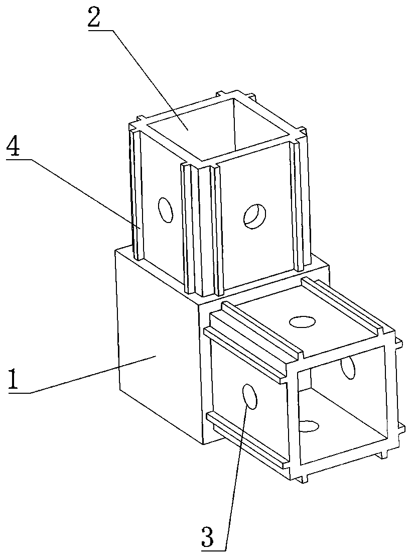
[0032] see Figure 1-Figure 5 As shown, this embodiment provides a built-in corner insert, including a mounting part 1 and two tubular corner parts 2, the mounting part 1 is provided with six mounting surfaces 8; one end of the corner part 2 is connected to the mounting part 1 The mounting surface 8 of the corner portion 2 is fixed, and the side surface of the corner portion 2 is provided with a connection structure. .

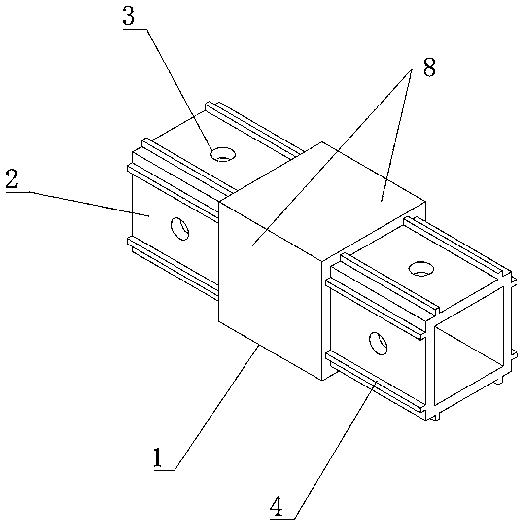
[0033] During specific implementation, the installation part 1 in this embodiment is a hollow hexahedron, and the six faces of the hexahedron are the six installation surfaces 8 of the installation part 1; see figure 1 , figure 2 , Figure 4 , Figure 5 As shown, the two corners 2 are respectively fixed to two adjacent installation surfaces 8 on the installation part 1, and at this time the two corners 2 are perpendicular to each other; see image 3 As shown, the two corner portions 2 can also be respectively fixed to two opposite mounting surfaces 8 on ...

Embodiment 2

[0039] see Figure 6 and Figure 7 As shown, the difference between this embodiment and Embodiment 1 is that the number of the corners 2 is three, and the three corners 2 are respectively fixed to any three mounting surfaces 8 on the mounting portion 1; between the three corners 2 The two are perpendicular to each other (see Figure 7 ) or the three corners 2 are coplanar (see Figure 6 ). Figure 6 and Figure 7 It only shows that the connection structure on the corner 2 is a through hole 3 and has a buffer edge 4, the structure of the corner 2 in this embodiment can also be the same as figure 1 or Figure 4 or Figure 5 The structure of the middle corner part 2 is the same.

Embodiment 3

[0041] see Figure 8 and Figure 9As shown, the difference between this embodiment and embodiment 1 is that the number of the corner portions 2 is four, and the four corner portions 2 are respectively fixed to any four mounting surfaces 8 on the mounting portion 1 . In this embodiment, there are two combinations of the corner part 2 and the mounting part 1, namely Figure 9 The four corners shown in 2 are coplanar, Figure 8 The four corners 2 shown in are not coplanar. Figure 8 and Figure 9 It only shows that the connection structure on the corner 2 is a through hole 3 and has a buffer edge 4, the structure of the corner 2 in this embodiment can also be the same as figure 1 or Figure 4 or Figure 5 The structure of the middle corner part 2 is the same.


PUM


Abstract

The invention relates to the technical field of mounting construction, and discloses a built-in corner plugin. The built-in corner plugin comprises a mounting part and a plurality of tubular corner parts, wherein six mounting surfaces are arranged on the mounting part; and one ends of the corner parts are fixed to the mounting faces of the mounting part, and connecting structures are arranged on the side faces of the corner parts. According to the built-in corner plugin, firm fixing of a square pipe is achieved through various forms of the connecting structures, frame connecting points is excessive in smoothness, the strength requirement of the connecting points can also be met, the mounting process is extremely simple, too many auxiliary tools are not needed in the mounting process, and the number of construction steps is small, so that the construction efficiency is favorably improved.

Description

technical field [0001] The invention relates to the technical field of installation and construction, in particular to a built-in corner plug-in. Background technique [0002] In the field of construction or industrial construction, frames are often used to support or set up work platforms. The frames are usually built from a large number of pipes. At present, the pipes of the frame are connected by welding, bolting or external joints. The installation process is cumbersome. There are many construction steps and the construction efficiency is not high. In addition, because the existing external joints have a relatively simple structure, they are often only applicable to specific occasions, and the scope of application is relatively narrow. Contents of the invention [0003] In order to solve the deficiencies of the prior art, the present invention provides a built-in corner plug-in with relatively simple installation process and favorable construction efficiency. [0004...

Claims


Application Information

Patent Timeline
Patent Type & Authority Applications(China)
IPC IPC(8): E04G7/26
CPCE04G7/26
Inventor 李奋勇
Owner 郑州倍安科技有限公司
Why Eureka
Try Eureka