
Concrete preparation pouring steel formwork

A technology for concrete and steel formwork, which is applied in the fields of formwork/formwork components, formwork/formwork/work frame, and on-site preparation of building components, etc. problems, to achieve the effect of increasing the support effect, increasing the integrity, and increasing the applicability

Active Publication Date: 2020-08-21
山东海德重工有限公司
View PDF11 Cites 6 Cited by
  • Summary
  • Abstract
  • Description
  • Claims
  • Application Information

AI Technical Summary

Problems solved by technology

[0003] Building pillars will be set in different dimensions according to different needs, such as common circular, square, and polygonal building pillars. For hexagonal building pillars, due to more sides, the stability of building steel formwork is poor during construction. , it is easy to cause the deformation of the building steel formwork, or the leakage of concrete due to the uneven butt joint of the side of the steel formwork. The existing problems in supporting the hexagonal building steel formwork are as follows:
[0004] 1. The splicing stability of the hexagonal steel formwork is poor, and the installation and disassembly steps of the formwork are relatively cumbersome, and the butt joint between the formwork is not dense, so there is a hidden danger of concrete leakage;
[0005] 2. The integrated connection between hexagonal steel formworks is impossible, which makes the integrity of the steel formwork poor, and each steel formwork can only be used for one type of building pillar

Method used


Image

  • Concrete preparation pouring steel formwork
  • Concrete preparation pouring steel formwork
  • Concrete preparation pouring steel formwork

Examples


Embodiment Construction

[0028] In order to make the technical means, creative features, objectives and effects achieved by the present invention easy to understand, the present invention will be further elaborated below in combination with specific diagrams. It should be noted that, in the case of no conflict, the embodiments in the present application and the features in the embodiments can be combined with each other.

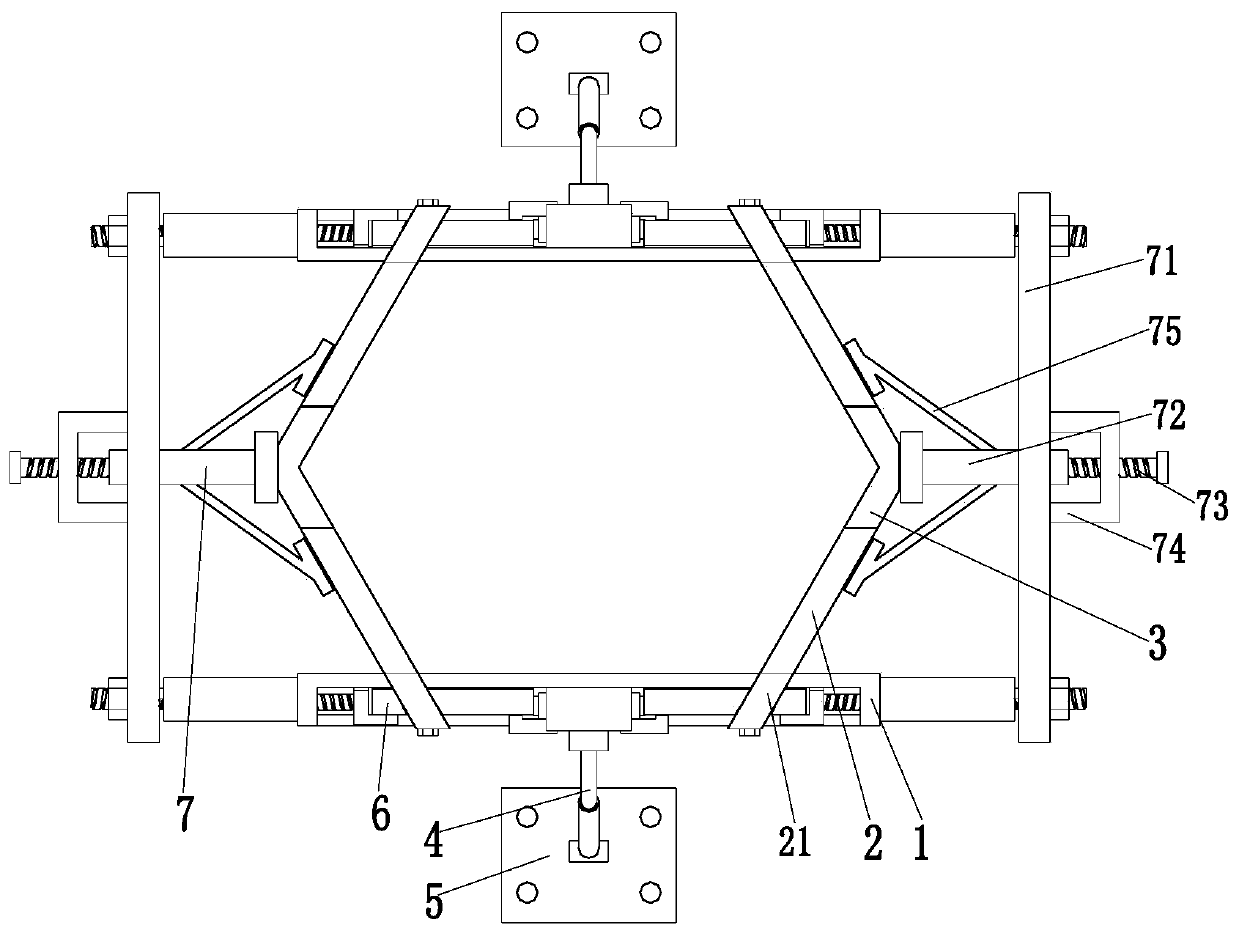
[0029] Such as Figure 1 to Figure 5As shown, a concrete preparation and pouring steel formwork includes a side support plate 1, an inclined support plate 2, a butt plate 3, a support rod 4, a support bottom plate 5, an adjustment mechanism 6 and a support mechanism 7, and the side support plate 1 The quantity is two, the side support plates 1 are arranged front and back, the outer surface of each side support plate 1 is provided with grooves, and the left and right sides of the middle part of each side support plate 1 are provided with a transverse chute 12, and the adjustment mech...


PUM


Abstract

The invention relates to a concrete preparation pouring steel formwork. The concrete preparation pouring steel formwork comprises two side supporting plates, inclined supporting plates, butt joint plates, supporting rods, a supporting bottom plate, an adjusting mechanism and a supporting mechanism, wherein a groove is formed in the outer side face of each side supporting plate; the adjusting mechanism is connected into the grooves in the side supporting plates; the left end and the right end of each side supporting plate are each connected with one inclined supporting plate; the inclined supporting plates are obliquely arranged; a positioning clamping groove is formed in the middle of the inner end of each inclined supporting plate; and the butt joint plates are distributed between the inner ends of the two adjacent inclined supporting plates at the left end of each side supporting plate and between the inner ends of the two adjacent inclined supporting plates at the right end of eachside supporting plate. The problems that when an existing hexagonal building steel formwork is supported, the splicing stability of the hexagonal steel formwork is poor, the formwork mounting and dismounting steps are complex, the hexagonal steel formworks cannot be integrally connected, and the integrity of the steel formwork is poor can be solved.

Description

technical field [0001] The invention relates to the technical field of building construction, in particular to a steel formwork for concrete preparation and pouring. Background technique [0002] Building pillars can play a role in stabilizing the building. The building pillars are generally constructed by concrete pouring. Before the concrete pouring of the building pillars, the steel frame needs to be bundled. The concrete is poured in the support structure formed by the formwork. [0003] Building pillars will be set in different dimensions according to different needs, such as common circular, square, and polygonal building pillars. For hexagonal building pillars, due to more sides, the stability of building steel formwork is poor during construction. , it is easy to cause the deformation of the building steel formwork, or the leakage of concrete due to the uneven butt joint of the side of the steel formwork. The existing problems in supporting the hexagonal building st...

Claims


Application Information

Patent Timeline
IPC IPC(8): E04G13/02E04G9/06E04G17/065
CPCE04G9/06E04G13/025E04G17/0655
Inventor 金双苏美琳
Owner 山东海德重工有限公司
Learn More