Concrete pouring equipment used for construction equipment

A kind of construction equipment and concrete technology, which is applied in the direction of construction, building structure, and construction material processing, etc. It can solve the problems that the concrete cannot be fully exported, intermittent, and affects the effect of pouring.

Inactive Publication Date: 2020-08-21
朱国文
View PDF0 Cites 0 Cited by
  • Summary
  • Abstract
  • Description
  • Claims
  • Application Information

AI Technical Summary

Problems solved by technology

[0002] In the past, people's buildings were poured by manual direct mixing of concrete. This process required continuous manual lifting, and this method was not practical for taller concrete pouring blocks, and it was time-consuming and laborious. Later, people introduced Concrete pouring equipment is installed, and the concrete is conveyed out by hydraulic pressure through concrete mixing. However, during the pouring process of the concrete pouring machine, its mixing body has only simple supports, which will cause uneven mixing and generate air bubbles during the mixing process, resulting in hydraulic pressure. When air bubbles are encountered when exporting concrete, the air bubbles will be exported together, and if the air bubbles are punctured during the export process, the delivery will be intermittent, which will affect the effect of pouring, and its suction port has only one set in the mixer on the connection block, so that the coagulation inside the equipment will not be fully exported

Method used


Image

  • Concrete pouring equipment used for construction equipment
  • Concrete pouring equipment used for construction equipment
  • Concrete pouring equipment used for construction equipment

Examples


Embodiment 1

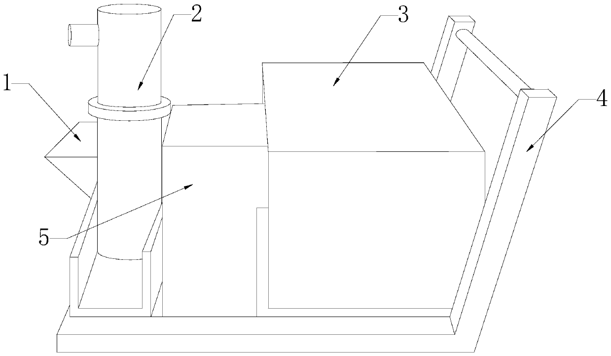
[0028] see Figure 1-Figure 4 , a concrete pouring equipment for construction equipment, the present invention provides a concrete pouring equipment for construction equipment, in view of the deficiencies in the prior art, the present invention is achieved through the following technical solutions: a concrete pouring equipment for construction equipment, its The structure includes a processor 1, a discharge pipe 2, a body 3, a handle 4, and a control box 5. The rear of the body 3 is provided with a handle 4, and the control box 5 is installed in front of the body 3. The processor 1 and The machine body 3 is mechanically connected, and the processor 1 is movably connected with the discharge pipe 2 through a connecting shaft.

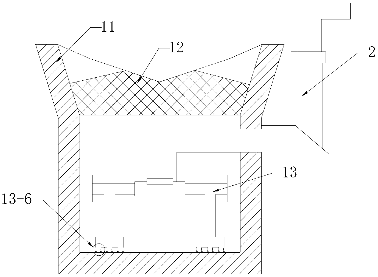
[0029] The processor 1 is composed of a cavity 11, a defoaming cavity 12, and an agitator 13, the cavity 11 is provided with a defoaming cavity 12, the agitator 13 is mechanically connected with the cavity 11, and the agitator 13 is movably connected wit...

Embodiment 2

[0036] see Figure 1-Figure 6 , a concrete pouring equipment for construction equipment, the present invention provides a concrete pouring equipment for construction equipment, in view of the deficiencies in the prior art, the present invention is achieved through the following technical solutions: a concrete pouring equipment for construction equipment, its The structure includes a processor 1, a discharge pipe 2, a body 3, a handle 4, and a control box 5. The rear of the body 3 is provided with a handle 4, and the control box 5 is installed in front of the body 3. The processor 1 and The machine body 3 is mechanically connected, and the processor 1 is movably connected with the discharge pipe 2 through a connecting shaft.

[0037] The processor 1 is composed of a cavity 11, a defoaming cavity 12, and an agitator 13, the cavity 11 is provided with a defoaming cavity 12, the agitator 13 is mechanically connected with the cavity 11, and the agitator 13 is movably connected wit...


PUM


Abstract

The invention discloses concrete pouring equipment used for construction equipment. A structure of the equipment includes a processing device, a discharge pipe, a machine body, a handle, and a controlbox, wherein the handle is disposed on the rear of the machine body. Through a mixer having a T-shaped structure on one side, the equipment can take the inner wall and the bottom of a cavity into account during mixing to achieve a complete mixing effect, a scraping body on the mixer can not only scrape off concrete attached to the inner wall of the cavity and also punctures bubbles to perform complete mixing; the surface of the periphery of the scraping body is surrounded by sharp puncturing blocks, both sides of the sharp puncturing blocks are smooth arc-shaped surfaces that are concave inward, and the scraping body is a spherical surface, and so, the concrete can slide down along the arc during rotation and a clamping phenomenon does not occur, and processing blocks of lower stirring blocks touch the bottom of the cavity, during rotation, outwardly-curved arc-shaped blocks on both sides can achieve mixing in a bottom scraping manner, and a clamping space of a connection part of theradian bending outward is small, and the arc-shaped sharp puncturing blocks at the connection part between the radian and material sucking mouths can prevent the concrete from getting stuck in gaps and cannot falling off.

Description

technical field [0001] The invention relates to the field of construction machinery, in particular to concrete pouring equipment for construction equipment. Background technique [0002] In the past, people's buildings were poured by manual direct mixing of concrete. This process required continuous manual lifting, and this method was not practical for taller concrete pouring blocks, and it was time-consuming and laborious. Later, people introduced Concrete pouring equipment is installed, and the concrete is conveyed out by hydraulic pressure through concrete mixing. However, during the pouring process of the concrete pouring machine, its mixing body has only simple supports, which will cause uneven mixing and generate air bubbles during the mixing process, resulting in hydraulic pressure. When air bubbles are encountered when exporting concrete, the air bubbles will be exported together, and if the air bubbles are punctured during the export process, the delivery will be in...

Claims


Application Information

Patent Timeline
Patent Type & Authority Applications(China)
IPC IPC(8): E04G21/04B28C5/16B28C5/08B08B9/087B01D33/333
CPCB01D33/333B08B9/0808B28C5/0806B28C5/16E04G21/04
Inventor 朱国文
Owner 朱国文
Why Eureka
Try Eureka