
Current sensor

A technology of current sensor and magnetic sensor, which is applied in the direction of only measuring current, voltage/current isolation, measuring current/voltage, etc. It can solve the problems of poor accuracy of current sensor and low sensitivity of Hall sensor, and achieve the effect of increasing sensitivity

Pending Publication Date: 2020-08-21
ACEINNA TRANSDUCER SYST CO LTD
View PDF0 Cites 1 Cited by
  • Summary
  • Abstract
  • Description
  • Claims
  • Application Information

AI Technical Summary

Problems solved by technology

For the traditional Hall effect based current sensor, the accuracy of the current sensor is poor due to the low sensitivity of the Hall sensor

Method used


Image

  • Current sensor
  • Current sensor
  • Current sensor

Examples


Embodiment Construction

[0022] In order to make the above objects, features and advantages of the present invention more comprehensible, the present invention will be further described in detail below in conjunction with the accompanying drawings and specific embodiments.

[0023] Reference herein to "one embodiment" or "an embodiment" refers to a particular feature, structure or characteristic that can be included in at least one implementation of the present invention. "In one embodiment" appearing in different places in this specification does not all refer to the same embodiment, nor is it a separate or selective embodiment that is mutually exclusive with other embodiments. Unless otherwise specified, the words connected, connected, and joined in this document mean that they are electrically connected directly or indirectly.

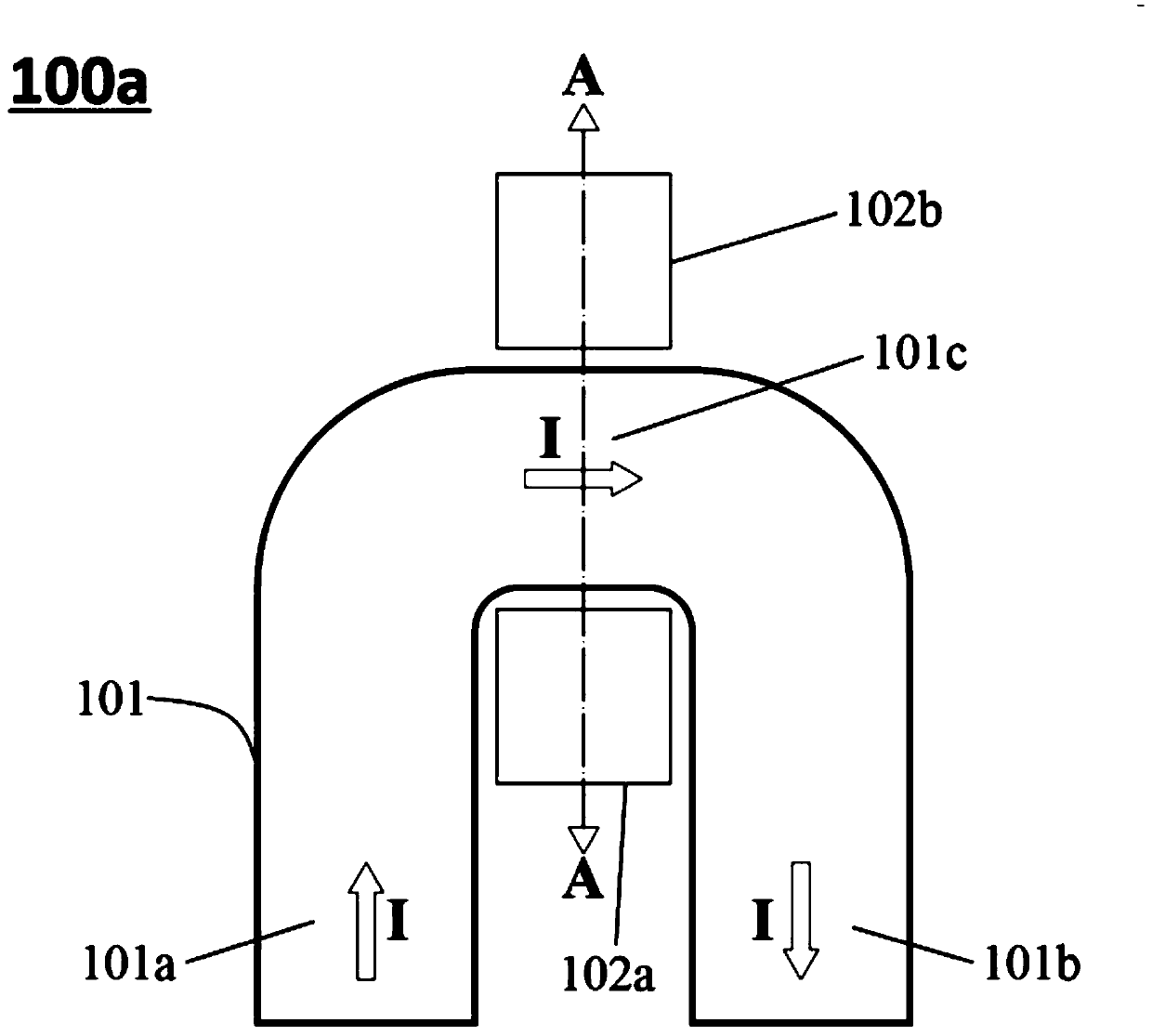
[0024] Please refer to figure 1 As shown, it is a schematic structural diagram 100a of a conventional current sensor. figure 1 The illustrated current sensor 100 a includ...


PUM


Abstract

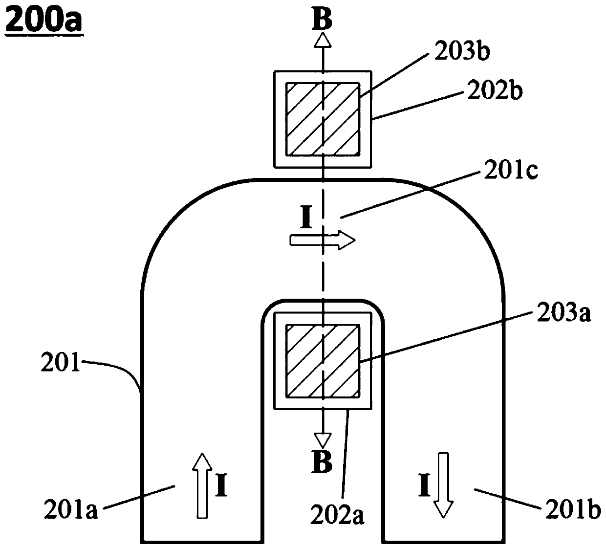
The invention provides a current sensor, which comprises a current-carrying conductor, a magnetic sensor and a soft magnet. The current-carrying conductor is used for providing a flowing channel for measured current; the magnetic sensor is located around the current-carrying conductor and detects the determined current according to a magnetic field at the magnetic sensor; and the soft magnet is positioned around the magnetic sensor and is used for amplifying a magnetic field generated by the current I in the current-carrying conductor at the magnetic sensor. Compared with the prior art, the current sensor provided by the invention comprises the current-carrying conductor, the magnetic sensor and the soft magnet, and the soft magnet plays a role in amplifying the magnetic field generated bythe current in the current-carrying conductor at the Hall sensor, so that the sensitivity of the current sensor is improved.

Description

【Technical field】 [0001] The invention relates to the technical field of current sensors, in particular to a current sensor with high precision and high bandwidth. 【Background technique】 [0002] Current sensors for measuring the magnitude of current are widely used in various electronic devices. For the traditional current sensor based on the Hall effect, the accuracy of the current sensor is poor due to the low sensitivity of the Hall sensor. [0003] Therefore, it is necessary to propose a technical solution to solve the above problems. 【Content of invention】 [0004] One of the objectives of the present invention is to provide a current sensor with high precision and high bandwidth. [0005] According to one aspect of the present invention, the present invention provides a current sensor, which includes a current-carrying conductor, a magnetic sensor and a soft magnetic body, the current-carrying conductor is used to provide a passage for the current to be measured; ...

Claims


Application Information

Patent Timeline
Patent Type & Authority Applications(China)
IPC IPC(8): G01R15/20G01R19/00
CPCG01R15/202G01R19/0092
Inventor 李大来蒋乐跃
Owner ACEINNA TRANSDUCER SYST CO LTD
Learn More