Cutting equipment for processing mechanical accessories

A technology of cutting equipment and processing machinery, which is applied in the direction of metal processing machinery parts, metal processing equipment, shearing machine equipment, etc., can solve the problems of shortening the service life of the blade, bulky cutting device, inconvenient cooling of the blade, etc., to prolong the service life, Improved cooling effect and easy operation

Inactive Publication Date: 2020-08-25
杨明清
View PDF5 Cites 5 Cited by
  • Summary
  • Abstract
  • Description
  • Claims
  • Application Information

AI Technical Summary

Problems solved by technology

[0004] The purpose of the present invention is to solve the disadvantages of the existing cutting device, which are bulky, extremely inconvenient to u

Method used


Image

  • Cutting equipment for processing mechanical accessories
  • Cutting equipment for processing mechanical accessories
  • Cutting equipment for processing mechanical accessories

Examples


Embodiment 1

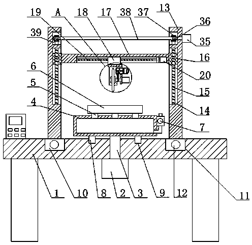
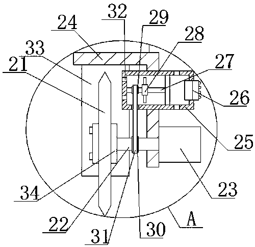
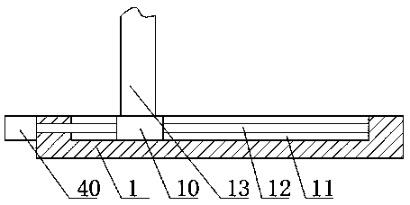
[0030] refer to Figure 1-5 , a cutting device for processing mechanical parts, including a processing plate 1, the top of the processing plate 1 is provided with two longitudinal drive mechanisms, both longitudinal drive structures are provided with vertical plates 13, between the two vertical plates 13 The same lifting plate 17 is slidably installed, the bottom of the lifting plate 17 is provided with a transverse drive structure, the transverse drive structure is connected with a fixing frame 24, the fixing frame 24 is provided with a cutting structure and a cooling structure, and the fixing frame 24 is provided with a dust blocking structure Plate 33, the top of the processing plate 1 is provided with a rotating structure, the rotating structure is connected with a placing box 4, the top of the placing box 4 is connected with a plurality of negative pressure pipes 5, and the same mechanical fitting 6 is connected to the plurality of negative pressure pipes 5 .

[0031] In...

Embodiment 2

[0041] refer to Figure 1-5 , a cutting device for processing mechanical parts, including a processing plate 1, the top of the processing plate 1 is provided with two longitudinal drive mechanisms, both longitudinal drive structures are provided with vertical plates 13, between the two vertical plates 13 The same lifting plate 17 is slidably installed, the bottom of the lifting plate 17 is provided with a transverse drive structure, the transverse drive structure is connected with a fixing frame 24, the fixing frame 24 is provided with a cutting structure and a cooling structure, and the fixing frame 24 is provided with a dust blocking structure Plate 33, the top of the processing plate 1 is provided with a rotating structure, the rotating structure is connected with a placing box 4, the top of the placing box 4 is connected with a plurality of negative pressure pipes 5, and the same mechanical fitting 6 is connected to the plurality of negative pressure pipes 5 .

[0042] In...


PUM


Abstract

The invention belongs to the technical field of cutting equipment, and particularly relates to cutting equipment for processing mechanical accessories. In allusion to the problems that an existing cutting device is bulky and extremely inconvenient to use, a blade is inconvenient to cool, and the service life of the blade is shortened, a solution is proposed as follows. The cutting equipment comprises a processing plate, two longitudinal drive mechanisms are arranged at the top of the processing plate, vertical plates are arranged on the two longitudinal drive mechanisms, and a same lifting plate is slidably installed between the two vertical plates; a horizontal drive structure is arranged at the bottom of the lifting plate, the horizontal drive structure is connected with a fixed frame, and a cutting structure and a cooling structure are arranged on the fixed frame; a dust board is arranged on the fixed frame, a rotating structure is arranged at the top of the processing plate, the rotating structure is connected with a placement box, and a plurality of negative pressure pipes communicate with the top of the placement box. The cutting equipment is convenient to operate and small in size, the blade is convenient to cool, and the service life of the blade is prolonged.

Description

technical field [0001] The present invention relates to the technical field of cutting equipment, in particular to a cutting equipment used for processing mechanical accessories. Background technique [0002] Machinery is a tool device that can help people reduce the difficulty of work or save labor. Items such as chopsticks, brooms and tweezers can be called machinery. They are simple machinery, while complex machinery is composed of two or more simple machinery. Composition, mechanical accessories need to use a cutting device when cutting. [0003] The existing cutting device is bulky, extremely inconvenient to use, and inconvenient to cool the blade, which shortens the service life of the blade. SUMMARY OF THE INVENTION [0004] The purpose of the present invention is to solve the shortcomings of the existing cutting device, which is bulky, extremely inconvenient to use, and inconvenient to cool the blade and shorten the service life of the blade. equipment. [0005]...

Claims


Application Information

Patent Timeline
IPC IPC(8): B23D19/00B23D33/00B23D33/02B23Q11/00B23Q11/10
CPCB23D19/00B23D33/00B23D33/02B23Q11/00B23Q11/10
Inventor 杨明清
Owner 杨明清
Why Eureka
Try Eureka