A light-duty soft material punching device

A soft material, punching technology, applied in the field of light soft material processing devices, can solve the problems of reducing production efficiency, difficult to meet production needs, difficult to locate the die, and achieves improved positioning accuracy, simple and lightweight structure, improved The effect of production efficiency

Inactive Publication Date: 2021-10-19
丁卫兵
View PDF8 Cites 0 Cited by
  • Summary
  • Abstract
  • Description
  • Claims
  • Application Information

AI Technical Summary

Problems solved by technology

Due to the light weight of the light soft material, the cutting tool often lifts the light soft material when cutting, which is not conducive to the processing of the light soft material on the workbench, and it is necessary to remove the light soft material, which reduces the production efficiency
At the same time, the dies used for punching are usually fixed and installed mechanically or by superglue. After installation, it is difficult to replace the dies, and it is also difficult to position the dies during installation.
When punching light soft materials for different products, different shapes of knives are required. The replacement of the existing knife die installation method is time-consuming and laborious, and it is difficult to meet the production needs.

Method used


Image

  • A light-duty soft material punching device
  • A light-duty soft material punching device
  • A light-duty soft material punching device

Examples


no. 1 example

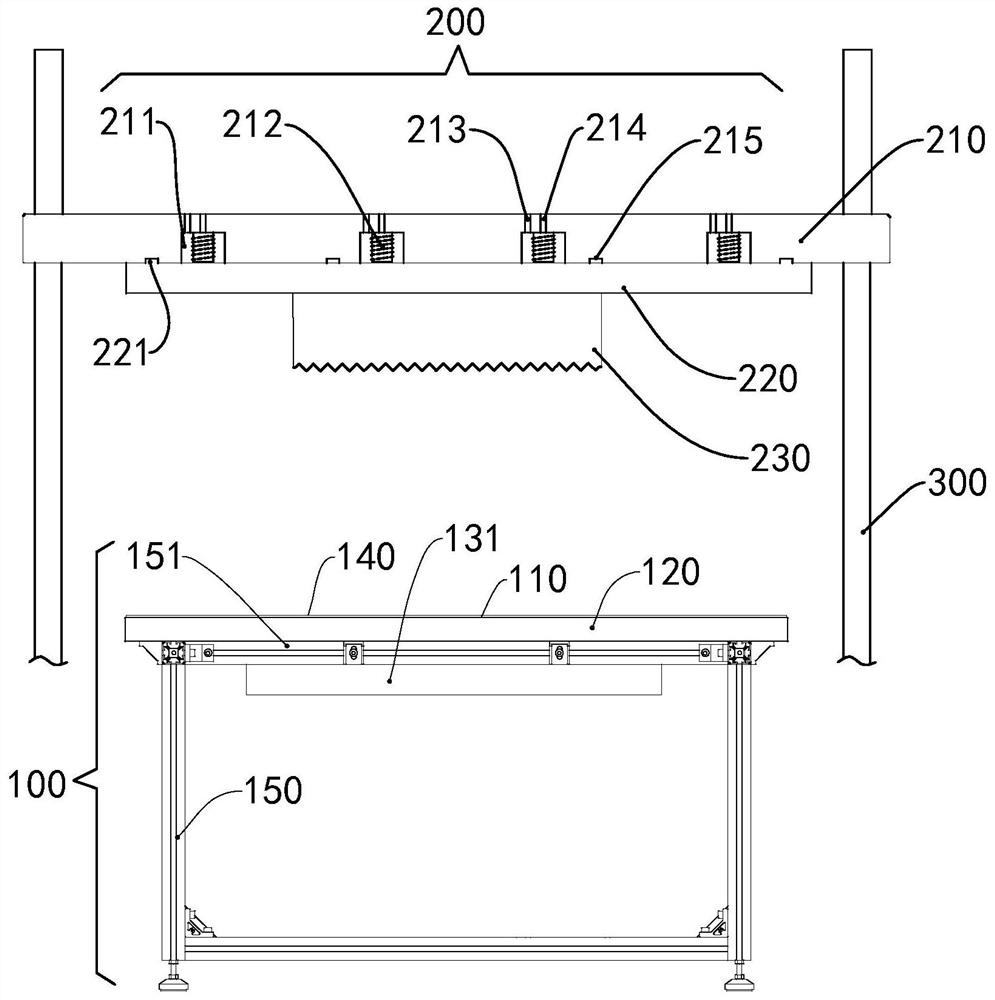
[0053] Such as Figure 1 to Figure 11 As shown, the lightweight soft material blanking device of this embodiment includes a worktable 100 and a die 200 , the die 200 is arranged above the workbench 100 and can move up and down relative to the workbench 100 . For example, the light-duty soft material blanking device may further include a guide column 300 , the guide column 300 is arranged vertically, and the cutting die 200 is slidably connected with the guide column 300 . The light-duty soft material blanking device may also include a driving member such as an oil cylinder, an air cylinder or a motor, etc., for pushing the knife die 200 to move up and down. The guide column 300 can be connected to an adjustment device, and the adjustment device is used to move the guide column 300 and the connected die 200 in a horizontal direction, such as front, rear, left, and right, so as to adjust the position of the die die 200 relative to the horizontal plane of the workbench 100 .

[...

no. 2 example

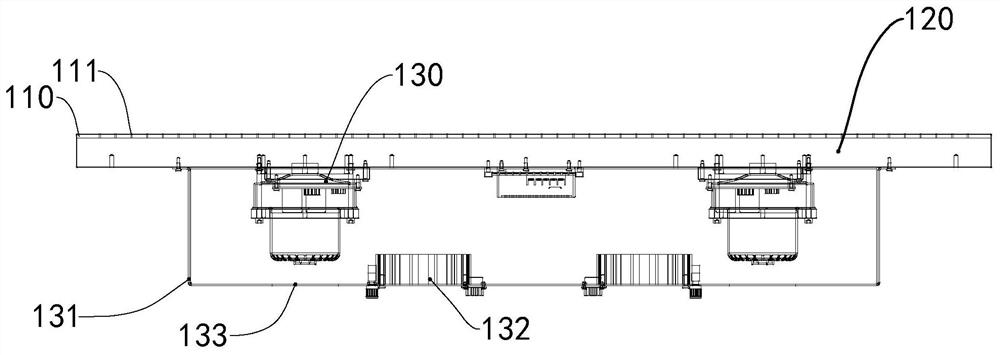
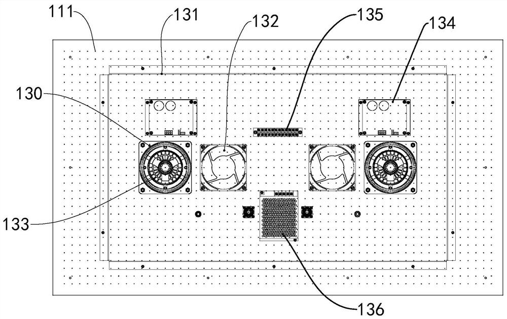
[0075] Such as Figure 12 to Figure 13 As shown, the structure of this embodiment is similar to that of the above-mentioned first embodiment, and the difference is that the table top 110 can be divided into a plurality of work areas, each work area is provided with a first air extraction hole 111, and the air groove 112 is formed on the upper surface of the table top 110. Connect the adjacent first air suction holes 111 in the same working area. An air extraction device is connected below each working area, and each air extraction device includes a chamber, a cover body, at least one blower fan and at least one instrument fan. Different chambers corresponding to different air extraction devices may be separated by a single integral chamber, and the different chambers are respectively connected to the cover body, the blower fan and the instrument fan.

[0076] In this embodiment, on the basis of the first embodiment, the countertop 110 is partitioned, and the negative pressure...

no. 3 example

[0078] Such as Figure 14 As shown, the structure of this embodiment is basically the same as that of the above-mentioned first embodiment, the difference is that the first limiting part in the die is the first limiting hole 216, and the second limiting part is the second limiting hole 222, that is, the positioning The board 210 is provided with a first limiting hole 216 , and the mounting plate 220 is provided with a second limiting hole 222 . The first limiting hole 216 is aligned with the second limiting hole 222 , and the limiting member 240 connects the first limiting hole 216 and the second limiting hole 222 . For example, the first limiting hole 216 and the second limiting hole 222 may be tapered through holes whose diameter decreases from top to bottom, and the limiting member 240 may be a conical pin. For example, one of the first limiting hole 216 and the second limiting hole 222 can be a threaded hole, the other can be a through hole, and the limiting member 240 ca...


PUM


Abstract

The invention relates to a light-duty soft material blanking device, which comprises a workbench and a cutting die above the workbench that can move up and down relative to the workbench; the workbench includes a workbench and at least one air extraction device; There is a first air extraction hole, and the air extraction device is connected to the first air extraction hole; the knife mold includes a positioning piece, a mounting piece and a knife, and the knife is connected to the mounting piece; the positioning piece is connected to an electromagnet, which is loosened by turning on and off the electromagnet Or adsorption mounting parts; the first limiting part is provided on the positioning part, and the second limiting part is provided on the mounting part, and the second limiting part is used to cooperate with the first limiting part to prevent the mounting part from moving relative to the positioning part. Move in at least one direction perpendicular to the direction of magnetic attraction. The light-duty soft material punching device of the present invention can prevent the light-duty soft material from being lifted up during punching, and can conveniently replace knives to improve production efficiency.

Description

technical field [0001] The invention relates to the technical field of light-duty soft material processing devices, in particular to a light-duty soft material punching device. Background technique [0002] Pearl cotton is usually a non-cross-linked closed-cell structure product formed by polyethylene foaming. It has water and moisture resistance, shock resistance, heat preservation, good plasticity, strong toughness, recyclability, environmental protection, strong impact resistance, and good chemical resistance. And many other advantages, it is widely used in the packaging of high-end fragile gifts, daily necessities and other products. The use of pearl cotton for packaging usually requires punching of sheet or plate-shaped light soft materials to form a placement slot that can match the shape of the product, so that it can surround the product, avoid product movement after packaging, and better protect the product. [0003] The blanking of light soft materials such as pea...

Claims


Application Information

Patent Timeline
Patent Type & Authority Patents(China)
IPC IPC(8): B26F1/38B26F1/44B26D7/02B26D7/20B26D7/26
CPCB26D7/018B26D7/20B26D7/2614B26F1/38B26F1/44
Inventor 丁卫兵
Owner 丁卫兵
Why Eureka
Try Eureka