Bulk material supply device for chip mounter

A technology for supply equipment and placement machines, applied in the direction of conveyor objects, transportation and packaging, etc., can solve the problems of waste materials, non-recyclable reuse, high cost, etc.

Pending Publication Date: 2020-08-25
深圳市恒鑫晟电子设备有限公司
View PDF0 Cites 0 Cited by
  • Summary
  • Abstract
  • Description
  • Claims
  • Application Information

AI Technical Summary

Problems solved by technology

When in use, the electronic components encapsulated in the reel are sent to the placement head in a certain order by a special feeder to be picked up. Among them, unpacking, pushing, alignment, and collection must be carried out before use. Operations such as bag sealing bring inconvenience to the patch operation; after use, the braided materials cannot be recycled and reused, which not only costs high, but also wastes materials
[0004] Therefore, the existing patch components cannot be directly mounted on the circuit board after feeding and sorting from the state of bulk materials, but need to be mounted on the circuit board after the process of tape winding, packaging and untaping, and pushing. The process increases the placement process, increases the cost of placement, reduces work efficiency, and also causes waste of braiding materials, so it needs to be improved

Method used


Image

  • Bulk material supply device for chip mounter
  • Bulk material supply device for chip mounter
  • Bulk material supply device for chip mounter

Examples


Embodiment Construction

[0025] The present invention will be described in further detail below in conjunction with the accompanying drawings.

[0026] This specific embodiment is only an explanation of the present invention, and it is not a limitation of the present invention. Those skilled in the art can make modifications to this embodiment as required after reading this specification, but as long as they are within the rights of the present invention All claims are protected by patent law.

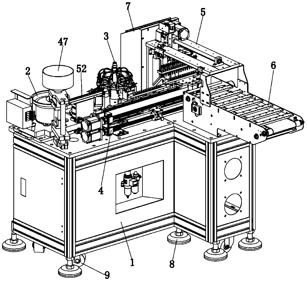
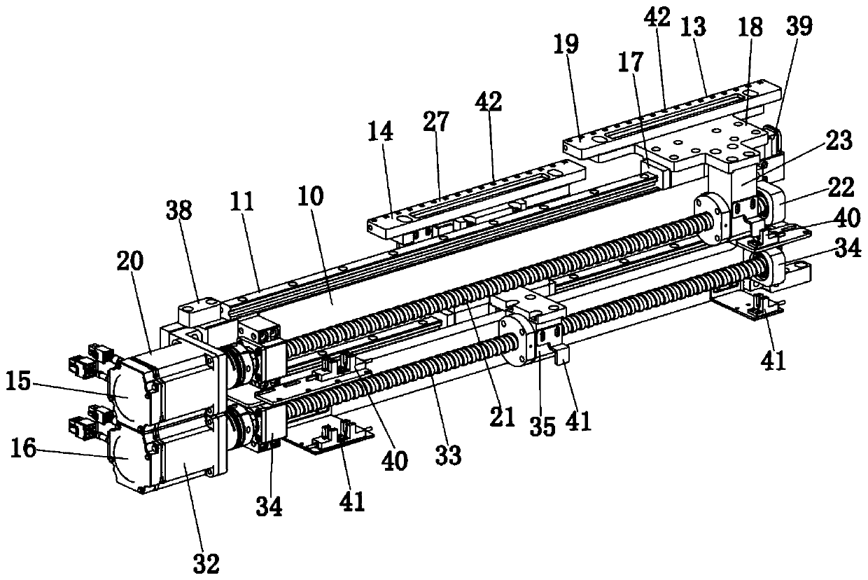
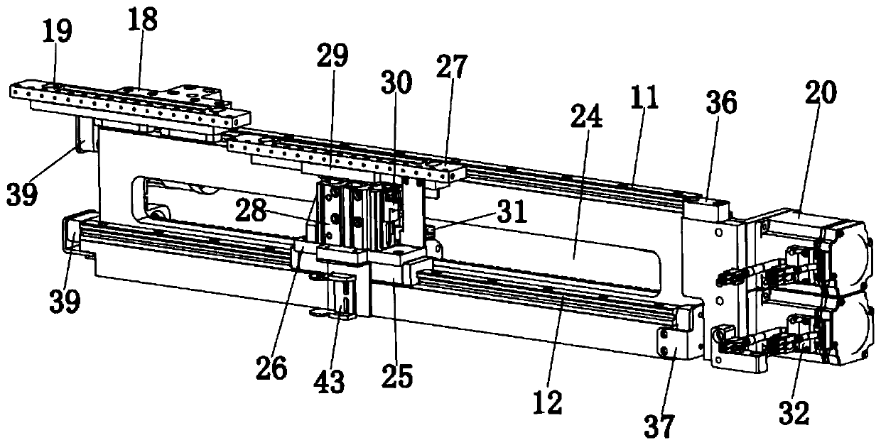
[0027] This embodiment relates to a bulk material supply equipment for a mounter, such as Figure 1-6 As shown, it includes: a frame 1 , a feeding mechanism 2 , a disc transfer mechanism 3 , a cross conveying mechanism 4 , a manipulator 5 , a discharging mechanism 6 and a control mechanism 7 .

[0028] Specifically, such as Figure 1-6 As shown, the feeding mechanism 2 is arranged on the frame 1 and is located on one side of the frame 1, and the feeding mechanism 2 is used to arrange the bulk materials in or...


PUM


Abstract

The invention provides a bulk material supply device for a chip mounter, and relates to the technical field of electronic component assembly equipment. The device comprises a rack, a feeding mechanism, a disc transfer mechanism, a cross conveying mechanism, a mechanical arm, a discharging mechanism and a control mechanism, wherein the feeding mechanism is arranged on the rack and positioned on oneside of the rack; the disc transfer mechanism is installed on the rack; the cross conveying mechanism is installed on the rack, one end of the cross conveying mechanism is in butt joint with the disctransfer mechanism, and the other end of the cross conveying mechanism is in butt joint with the mechanical arm; one end of the mechanical arm is fixedly installed on the rack; one end of the discharging mechanism is fixedly installed on the rack, and the other end of the discharging mechanism extends to the side away from the rack to be in butt joint with a discharging port of the chip mounter;and the control mechanism is used for controlling the feeding mechanism, the disc transfer mechanism, the cross conveying mechanism, the mechanical arm and the discharging mechanism to work in sequence. According to the technical scheme, the bulk material supply device has the advantages of being simple in chip mounting process, low in chip mounting cost and high in bulk material supply efficiency.

Description

technical field [0001] The invention relates to the technical field of electronic component assembly equipment, in particular to a bulk material supply equipment for a placement machine. Background technique [0002] With the advancement of electronic technology and the rapid development of electronic product manufacturing industry, the processing technology of mounting electronic components on circuit boards has become more and more adopted by many electronic manufacturers. [0003] At present, most SMT components are packaged into reels in the form of braid. When in use, the electronic components encapsulated in the reel are sent to the placement head in a certain order by a special feeder to be picked up. Among them, unpacking, pushing, alignment, and collection must be carried out before use. Operations such as bag sealing bring inconvenience to the patch operation; after use, the braided material cannot be recycled and reused, which not only costs high, but also wastes...

Claims


Application Information

Patent Timeline
Patent Type & Authority Applications(China)
IPC IPC(8): B65G47/52B65G47/90B65G47/74
CPCB65G47/52B65G47/74B65G47/90
Inventor 郑时雷
Owner 深圳市恒鑫晟电子设备有限公司
Why Eureka
Try Eureka