Flexible conveying device combining self-rotation with co-rotation and film coating machine cavity with same

A technology of transmission device and public rotation, which is applied in the direction of sputtering plating, ion implantation plating, vacuum evaporation plating, etc. It can solve the problems affecting the installation of the overall coating machine and the structure is too large, and achieves simple operation and small structure volume Effect

Active Publication Date: 2020-08-25
WUHAN JIUYI INTELLIGENT TECH CO LTD
View PDF5 Cites 2 Cited by
  • Summary
  • Abstract
  • Description
  • Claims
  • Application Information

AI Technical Summary

Problems solved by technology

[0006] In order to solve the technical problem that the existing male-autorotation workpiece rack structure is too large and affect the installation of the overall coating machine, the invention provides a flexible male-autorotation transmission device and a coating machine cavity with the device

Method used


Image

  • Flexible conveying device combining self-rotation with co-rotation and film coating machine cavity with same
  • Flexible conveying device combining self-rotation with co-rotation and film coating machine cavity with same
  • Flexible conveying device combining self-rotation with co-rotation and film coating machine cavity with same

Examples


Embodiment 1

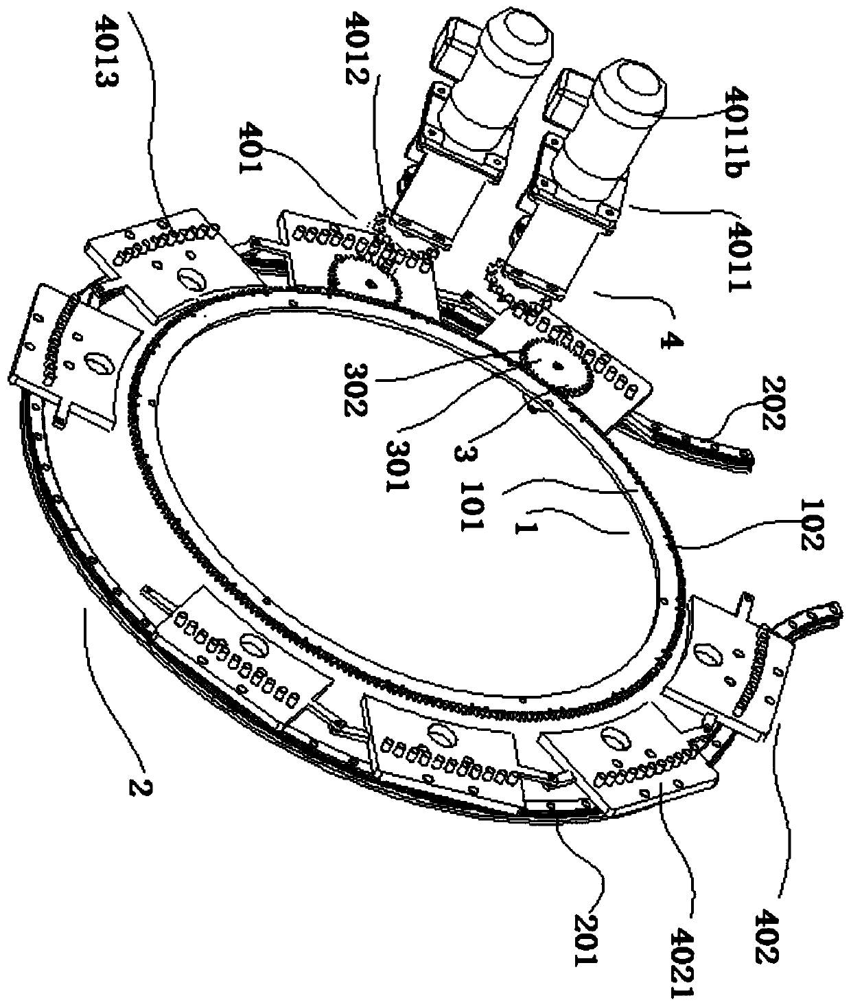
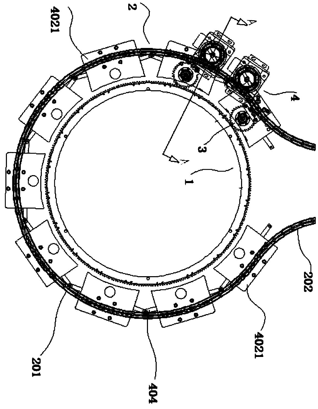
[0036] A flexible revolution transmission device A, such as Figure 1 to Figure 5 As shown, it includes: fixed tooth disc 1; flexible track 2, the flexible track 2 is set on the outer ring of the fixed tooth disc 1, the fixed track can be designed in advance according to the working track, and the variable track can also be designed to work a plurality of self-rotating roulettes 3, the self-rotating roulettes 3 are installed between the flexible track 2 and the fixed sprocket 1, and are in contact with the fixed sprocket 1 to generate friction The driving mechanism 4 is installed on the flexible track 2 and connected with the self-rotating wheel 3, and the self-rotating wheel 3 is driven by the driving mechanism 4 along the flexible track 2 Carry out motion, at the same time, due to the interaction force between the self-rotating wheel 3 and the fixed tooth disc 1, the self-rotating wheel 3 also rotates while moving along the flexible track 2; the mounting rod 5, the mounting ...

Embodiment 2

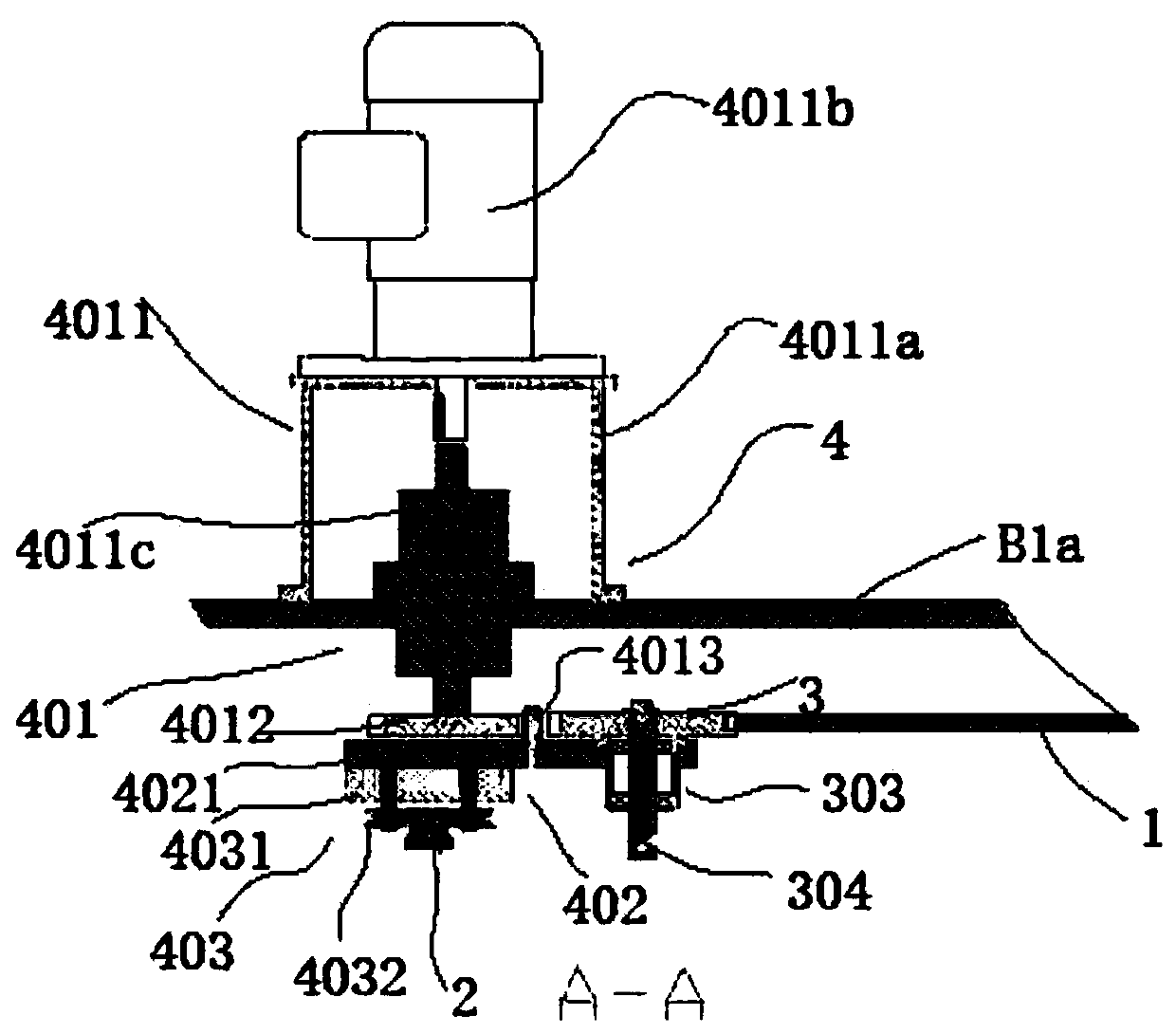
[0043] A coating machine single chamber B, such as Figure 4 ~ Figure 6 As shown, it includes: a cavity body B1, a cavity door (not shown in the figure), the cavity body B1 includes a cavity body top side B1a and a cavity body side B1b surrounding the cavity body top side B1a, and the cavity body The side B1b is provided with an opening B2, the cavity door is installed at the opening B2 of the cavity body, and the top side B1a of the cavity body is equipped with the flexible male and self-rotating upper transmission device A of Embodiment 1. In this embodiment, the top side of the cavity body B1a has a mounting hole for the transmission device, the power motor 4011b and the motor mounting seat 4011a are installed outside the top side of the chamber body B1a, the magnetic fluid 4011c is installed inside the motor mounting seat 4011a and is vacuum-tightly connected to the power sprocket 4012 through the transmission device mounting hole , The power sprocket 4012, the mounting ba...

Embodiment 3

[0046] A multi-cavity coating machine, such as Figure 4 ~ Figure 7 As shown, the multi-chamber body of the coating machine is formed by splicing multiple single-chamber bodies B of the coating machine through the vacuum isolation valve C. In this embodiment, the vacuum isolation valve C used is a plug valve, wherein each coating machine The single cavity includes: a cavity body B1 and a cavity door (not shown in the figure), the cavity body B1 includes a cavity body top side B1a and a cavity body side B1b surrounding the cavity body top side B1a, and the cavity body The side B1b is symmetrically provided with two openings B2, the chamber door is installed at the opening B2 of the chamber body, the vacuum isolation valve C is spliced ​​at the chamber door, and the top side B1a of the chamber body is installed by the above-mentioned flexible male rotation transmission device A, Refer to Example 2 for the installation method of flexible male and self-rotating upper transmission ...


PUM


Abstract

The invention provides a flexible conveying device combining self-rotation with co-rotation and a film coating machine cavity with the same. The conveying device comprises a fixed tooth plate, a flexible track, a plurality of self-rotating wheel plates, a driving mechanism and mounting rods, wherein the flexible track is arranged on the outer ring of the fixed tooth plate; the self-rotating wheelplates are mounted between the flexible track and the fixed tooth plate and in meshing contact with the fixed gear plate through gears; the driving mechanism is mounted on a top plate of a vacuum cavity through a magnetic fluid and in meshing contact with chain teeth on each self-rotating wheel plate through a chain wheel; and the mounting rods are connected to the self-rotating wheel plates. Theconveying device has the beneficial effects that a chain wheel track design scheme is adopted, the size of the device is reduced, and the installation of other functional structures and devices in thevacuum cavity is facilitated; the film-coating co-rotation and self-rotation operation in the single cavity can be achieved, mounted pieces can enter and exist the single cavity, the co-rotation andself-rotation operation of the single cavity in the multiple cavities can be achieved, and automatic workpiece exchange among the multiple cavities can be achieved; the flexible track can be changed to meet the different needs of production; and the whole process can be controlled automatically, and the operation is simple.

Description

technical field [0001] The invention belongs to the field of coating technology, and in particular relates to a flexible male-rotation transmission device and a coating machine chamber equipped with the device. Background technique [0002] Vacuum coating has been widely used in the fields of life and production, especially in the fields of decorative coating, optical coating, electronic product coating and architectural glass coating. When coating, the substrate and the target are placed in the same vacuum chamber, and the surface components of the target are evaporated in the form of atomic groups or ions by heating and other means, and settle on the surface of the substrate to form a thin film through the film forming process. [0003] During mass production of decorative films and coatings of electronic gadgets, the workpiece will rotate relative to the cathode with the workpiece frame in the vacuum cavity, which is conducive to the uniform film formation and mass produc...

Claims


Application Information

Patent Timeline
Patent Type & Authority Applications(China)
IPC IPC(8): C23C14/50
CPCC23C14/505
Inventor 郭爱云朱选敏
Owner WUHAN JIUYI INTELLIGENT TECH CO LTD
Why Eureka
Try Eureka