
Lifting lug cable clamp

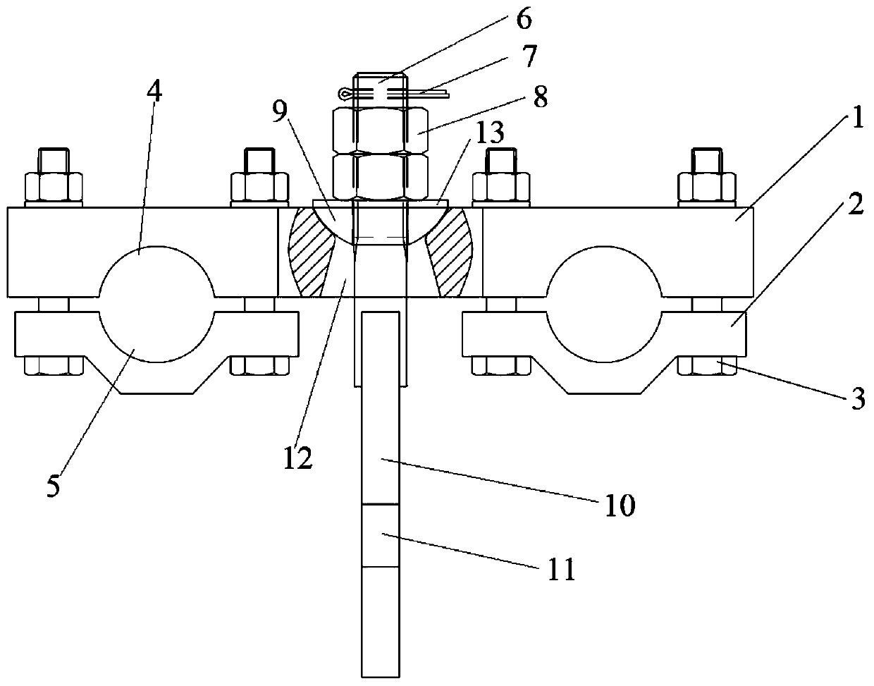
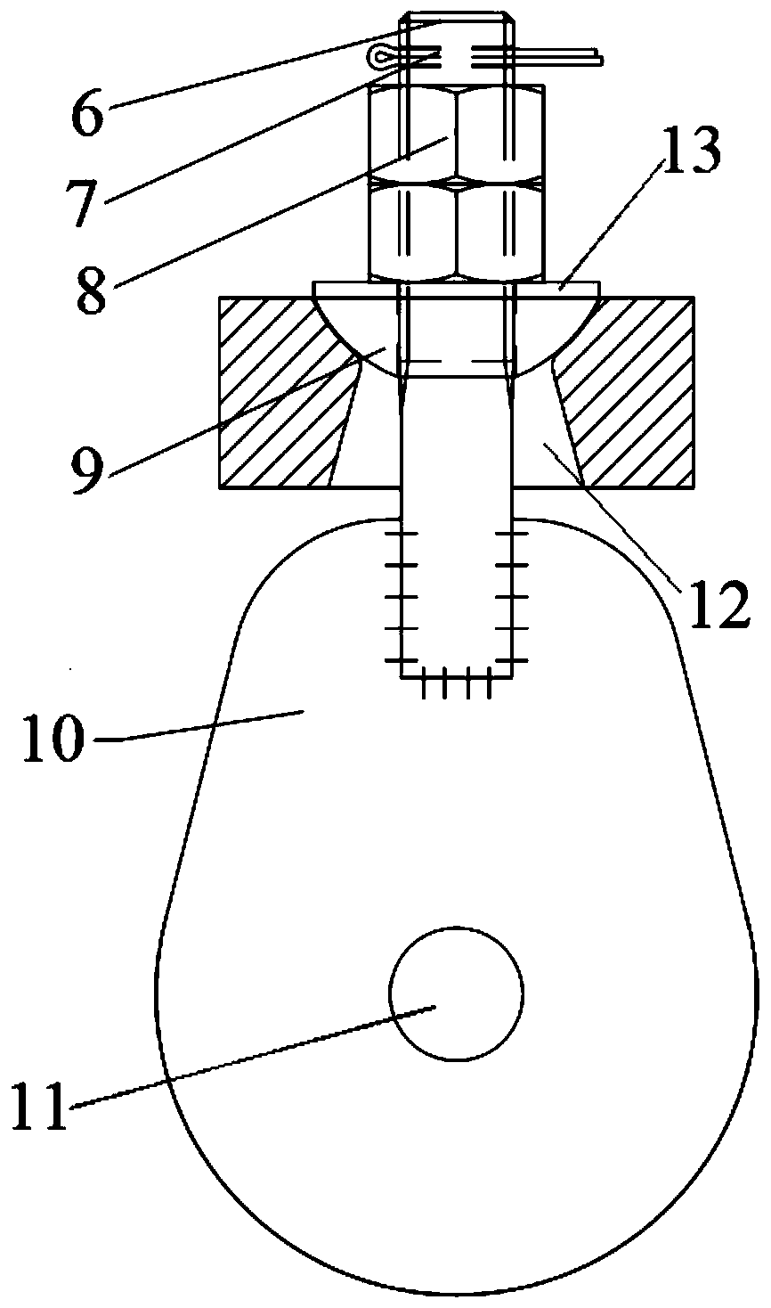
A technology of cable clips and lifting lugs, applied in special structures, building components, etc., can solve the problems of increased weight, increased size of cable clips, and short life, and achieve the effects of prolonging life, avoiding bending moments, and reducing bending-resistant structures

Pending Publication Date: 2020-08-25
BEIJING INST OF ARCHITECTURAL DESIGN
View PDF0 Cites 0 Cited by
  • Summary
  • Abstract
  • Description
  • Claims
  • Application Information

AI Technical Summary

Problems solved by technology

[0002] With the development of modern long-span buildings towards lightweight, more and more cable-net structure systems are used in building structures. Usually, the structural rigidity of cable-net is smaller than that of conventional steel structures. Large deformation will occur under snow load, because the deformation of the cable will deform together with the cable clip, resulting in the structure of the pull lug on the cable clip is no longer in the vertical direction, while the tension on the pull lug is in the vertical direction, so the pull There will be a bending moment at the connection position between the lug and the cable clamp. Usually, in such a situation, the design will increase the ribs perpendicular to the direction of the ear plate to resist the bending moment, which leads to an increase in the size and weight of the cable clamp. When such a When the number of cable clips is large, it will bring additional load to the entire cable net structure, and the economy will decrease; at the same time, when the additional bending moment is large, the safety of the ear plate will also be significantly reduced
This leads to the structure of the cable clip of the lifting lug being easily damaged and having a short service life

Method used


Image

  • Lifting lug cable clamp
  • Lifting lug cable clamp
  • Lifting lug cable clamp

Examples


Embodiment Construction

[0022] Exemplary embodiments of the present invention are described below in conjunction with the accompanying drawings, which include various details of the embodiments of the present invention to facilitate understanding, and they should be regarded as exemplary only. Accordingly, those of ordinary skill in the art will recognize that various changes and modifications of the embodiments described herein can be made without departing from the scope and spirit of the invention. Also, descriptions of well-known functions and constructions are omitted in the following description for clarity and conciseness.

[0023] In this article, the terms "up" and "down" that indicate relative positional relationship are based on figure 1 and figure 2 point of view.

[0024] The lug clip of the present invention includes a main body mechanism, a connecting mechanism and a movable mechanism, wherein the main mechanism is provided with a through hole, and the connecting mechanism passes th...


PUM


Abstract

The invention discloses a lifting lug cable clamp which comprises a main body mechanism, a connecting mechanism and a moving mechanism. The main body mechanism is provided with a through hole. The connecting mechanism sequentially penetrates through the moving mechanism and the through hole and then is connected with the main body mechanism. The moving mechanism is at least partially arranged in the through hole. The moving mechanism is movably connected with the main body mechanism. When the lifting lug cable clamp is used, the main body mechanism is connected with a pulling cable, when the pulling cable inclines due to outer force, the moving mechanism slides in the through hole in the main body mechanism, thus it is ensured that the connecting mechanism is still in the vertical direction, then bending moment among all the mechanisms of the lifting lug cable clamp is avoided, unnecessary bend resisting structures are reduced, and the lifting of the lifting lug cable clamp is prolonged.

Description

technical field [0001] The invention relates to the technical field of cable structure construction, in particular to a lifting ear cable clip. Background technique [0002] With the development of modern long-span buildings towards lightweight, more and more cable-net structure systems are used in building structures. Usually, the structural rigidity of cable-net is smaller than that of conventional steel structures. Large deformation will occur under snow load, because the deformation of the cable will deform together with the cable clip, resulting in the structure of the pull lug on the cable clip is no longer in the vertical direction, while the tension on the pull lug is in the vertical direction, so the pull There will be a bending moment at the connection position between the lug and the cable clamp. Usually, in such a situation, the design will increase the ribs perpendicular to the direction of the ear plate to resist the bending moment, which leads to an increase i...

Claims


Application Information

Patent Timeline
Patent Type & Authority Applications(China)
IPC IPC(8): E04B1/34
CPCE04B1/34
Inventor 王哲
Owner BEIJING INST OF ARCHITECTURAL DESIGN
Learn More