Variable optical flow FPGA implementation method and system, storage medium and terminal

An implementation method and spectroscopic technology, applied in image data processing, complex mathematical operations, instruments, etc., can solve the problems of difficult architectural design, high implementation difficulty, slow running speed, etc., to shorten application development time, improve computing speed, and easily cropped effect

Active Publication Date: 2020-08-25
XIDIAN UNIV
View PDF3 Cites 0 Cited by
  • Summary
  • Abstract
  • Description
  • Claims
  • Application Information

AI Technical Summary

Problems solved by technology

[0004](1) The computational complexity of the current variational optical flow technology is quite high, the implementation based on high-level language runs slowly, and the application scenarios are limited
[0005](2) The traditional FPGA development method is difficult to implement, the architecture design is difficult, and it is difficult to meet the rapid update iteration of the algorithm
[0009](3) Traditional FPGA development uses hardware description language to describe the hardware structure of the algorithm, but FPGA development requires experienced hardware engineers to implement, usually FPGA development engineers work with The communication between algorithm engineers needs to waste a lot of time

Method used


Image

  • Variable optical flow FPGA implementation method and system, storage medium and terminal
  • Variable optical flow FPGA implementation method and system, storage medium and terminal
  • Variable optical flow FPGA implementation method and system, storage medium and terminal

Examples


Embodiment Construction

[0061] In order to make the object, technical solution and advantages of the present invention more clear, the present invention will be further described in detail below in conjunction with the examples. It should be understood that the specific embodiments described here are only used to explain the present invention, not to limit the present invention.

[0062] Aiming at the problems existing in the prior art, the present invention provides a variational optical flow FPGA implementation method, system, storage medium, and terminal. The present invention will be described in detail below in conjunction with the accompanying drawings.

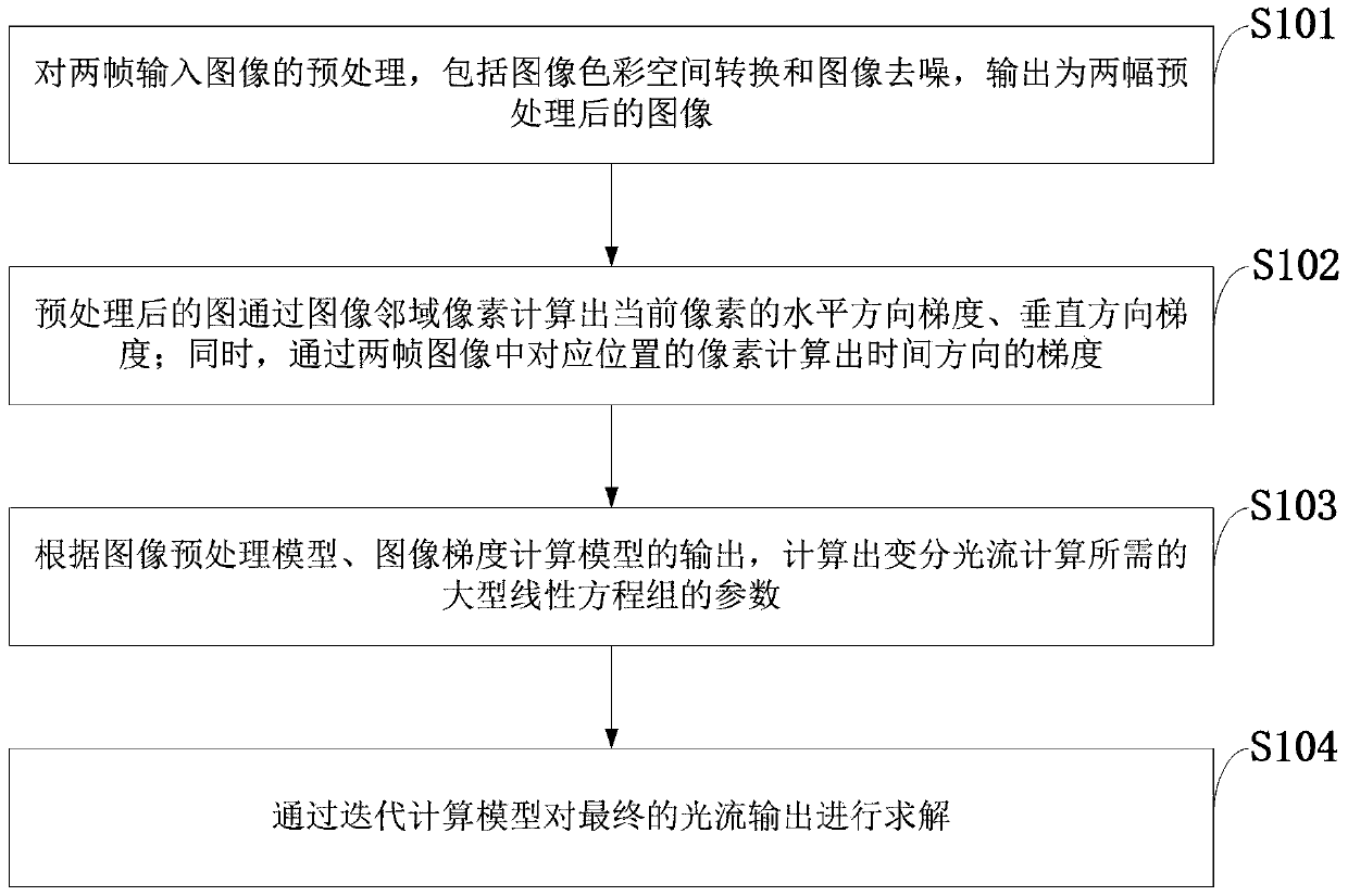
[0063] Such as figure 1 As shown, the variational optical flow FPGA implementation method provided by the present invention comprises the following steps:

[0064] S101: Preprocessing two frames of input images, including image color space conversion and image denoising, and outputting two preprocessed images;

[0065] S102: Calculate the ho...


PUM


Abstract

The invention belongs to the technical field of computer vision processing, and discloses a variational optical flow FPGA implementation method and system, a storage medium and a terminal. The methodcomprises the steps: carrying out the preprocessing of two frames of input images, including image color space conversion and image denoising, and outputting two preprocessed images; calculating the horizontal direction gradient and the vertical direction gradient of the current pixel of the preprocessed image through image neighborhood pixels; meanwhile, calculating the gradient in the time direction through pixels at the corresponding positions in the two frames of images; according to the output of the image preprocessing model and the output of the image gradient calculation model, calculating parameters of a large linear equation set required by variational optical flow calculation; and solving the final optical flow output through an iterative computation model. According to the method, the application and development time of the optical flow algorithm on FPGA hardware can be greatly shortened, all modules are independent of one another and are easy to cut, expand and maintain, the operation speed of the variational optical flow algorithm can be greatly increased, and the purpose of real-time application can be achieved.

Description

technical field [0001] The invention belongs to the technical field of computer vision processing, and in particular relates to a variational optical flow FPGA implementation method, system, storage medium, and terminal. Background technique [0002] At present, computer vision is a subject that mainly studies how to use images for expression. As a branch of computer vision, optical flow estimation is a widely used pixel motion representation method, and it is one of the most basic and extensive problems in the field of computer vision. The current mainstream optical flow estimation method is the optical flow algorithm based on variational optimization technology. Variational optimization technology describes the optical flow estimation problem as the minimization problem of the target energy function. By solving the target energy function, the final problem is transformed into a solution problem of a very large linear equation. Typical variational optical flow techniques ...

Claims


Application Information

Patent Timeline
IPC IPC(8): G06T1/20G06T5/00G06F30/331G06F17/11
CPCG06F17/11G06T1/20G06F30/331G06T5/70
Inventor 贾媛李鑫李娇娇宋彬王养利李云松
Owner XIDIAN UNIV
Why Eureka
Try Eureka