
Cluster type obstacle synchronization method

An obstacle and cluster technology, which is applied to services based on a specific environment, traffic control systems for road vehicles, instruments, etc., can solve the problem of limited processing capacity of single-vehicle processing equipment, hazards of vehicles and other traffic facilities, and inability to process environmental perception information. and other problems, to achieve the effect of facilitating timely processing and delivery, reducing computational burden, and solving driving blind spots

Active Publication Date: 2020-08-25
北京踏歌智行科技有限公司
View PDF14 Cites 0 Cited by
  • Summary
  • Abstract
  • Description
  • Claims
  • Application Information

AI Technical Summary

Problems solved by technology

[0003] In recent years, traffic accidents caused by self-driving vehicles have occurred frequently. The reason lies in the following limitations of bicycle perception: first, due to the limitation of sensor installation locations, bicycle perception equipment has detection blind spots; second, the processing capacity of bicycle processing equipment is limited , unable to process massive environmental perception information
For fixed obstacles, passing vehicles need to be calculated and repeatedly identified, which will increase the calculation burden of the vehicle, and there will also be restrictions on conditions such as field of view, and there will be situations where obstacles have been identified but there is not enough time to respond. May cause great harm to vehicles and other traffic facilities

Method used


Image

  • Cluster type obstacle synchronization method
  • Cluster type obstacle synchronization method

Examples


Embodiment 1

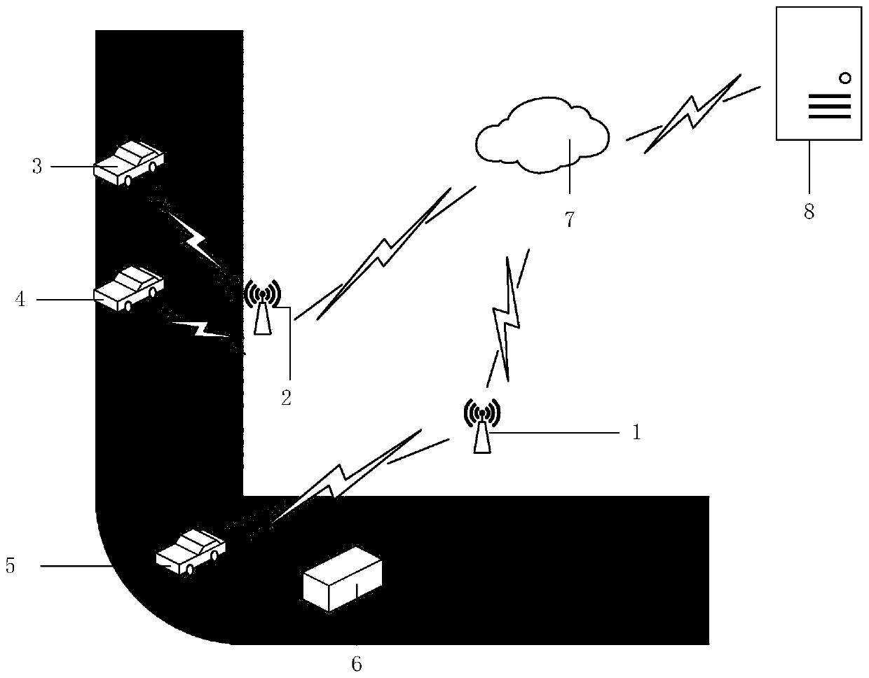
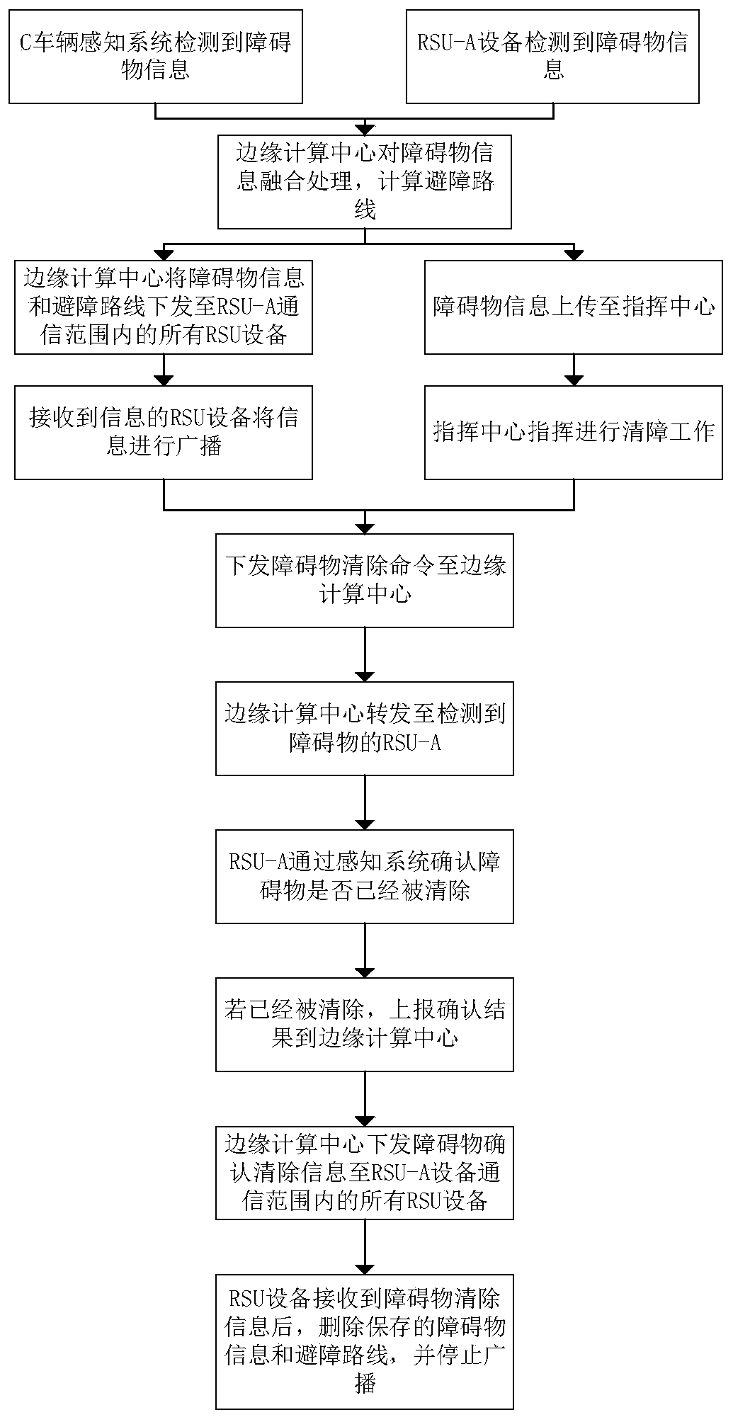
[0036] Such as figure 1 As shown, RSU-A device 1 and RSU-B device 2 are set on the road, A vehicle 3 and B vehicle 4 only have V2X communication capabilities, A vehicle 3 and B vehicle 4 are within the communication range of RSU-B device 2, The C vehicle 5 has environment awareness capability and V2X communication capability, and the C vehicle 5 is within the communication range of the RSU-A device 1 . It is assumed that an obstacle appears within the detection range of RSU-A device 1 and there is no obstacle within the detection range of RSU-B device 2 . A clustered obstacle synchronization method provided by Embodiment 1 of the present invention, such as figure 2 shown, including the following steps:

[0037] Step 1: The RSU-A device 1 detects the information of the obstacle 6 on the road through the perception system, and reports the information of the obstacle 6 to the edge computing center 7 through the mobile network; at the same time, the C vehicle 5 also perceives t...


PUM


Abstract

The invention discloses a cluster type obstacle synchronization method, which can effectively solve aproblem of a driving blind area and improve the perception capability of a vehicle by synchronizingRSU equipment and the obstacle detection information of the vehicle with environmental perception capability. After the obstacle information is determined, an obstacle avoidance route is planned through the edge calculation center, so the calculation burden of the vehicle-mounted terminal can be effectively reduced, the edge computing center issues the obstacle information and the obstacle avoidance route to the RSU device, the RSU device broadcasts the obstacle information and the obstacle avoidance route, and passing vehicles can avoid obstacles in advance after receiving the obstacle information, so safety of the vehicles is improved. The method is advantaged in that perfect barrier information reporting, issuing, clearing confirmation and updating processes are established, so the command center can process and issue the road condition information in time, through the cluster type obstacle synchronization method provided by the invention, the vehicle only needs to carry the V2X communication module, and the obstacle information issued by the RSU equipment is combined, so the vehicle can avoid obstacles in advance.

Description

technical field [0001] The invention relates to the technical field of automatic driving, in particular to a clustered obstacle synchronization method. Background technique [0002] With the continuous development of autonomous driving technology, various sensors have become an important part of the automatic driving system. Common sensors include lidar, millimeter-wave radar, monocular and binocular cameras, etc. [0003] In recent years, traffic accidents caused by self-driving vehicles have occurred frequently. The reason lies in the following limitations of bicycle perception: first, due to the limitation of sensor installation locations, bicycle perception equipment has detection blind spots; second, the processing capacity of bicycle processing equipment is limited , unable to process massive environmental perception information. [0004] The existing bicycle perception technology is an independent system for detecting obstacles, and there are cases of misidentificat...

Claims


Application Information

Patent Timeline
IPC IPC(8): G08G1/0967G08G1/16H04W4/40
CPCG08G1/096725G08G1/165G08G1/166G08G1/167H04W4/40
Inventor 路杰锋麻正黄立明
Owner 北京踏歌智行科技有限公司
Learn More