
Die bonding equipment

A technology for die bonding and equipment, which is applied in semiconductor/solid-state device manufacturing, electrical components, circuits, etc., can solve problems such as poor die bonding accuracy, and achieve the effects of improving die bonding accuracy, reducing displacement deviation, and reducing the range of motion

Active Publication Date: 2020-08-25
中山市新益昌自动化设备有限公司
View PDF8 Cites 3 Cited by
  • Summary
  • Abstract
  • Description
  • Claims
  • Application Information

AI Technical Summary

Problems solved by technology

[0003] The purpose of the present invention is to overcome the deficiencies of the above-mentioned prior art, and to provide a die-bonding equipment, which aims to solve the problem of poor die-bonding precision

Method used


Image

  • Die bonding equipment
  • Die bonding equipment
  • Die bonding equipment

Examples


Embodiment Construction

[0025] In order to make the object, technical solution and advantages of the present invention clearer, the present invention will be further described in detail below in conjunction with the accompanying drawings and embodiments. It should be understood that the specific embodiments described here are only used to explain the present invention, not to limit the present invention.

[0026] An embodiment of the present invention provides a crystal bonding device.

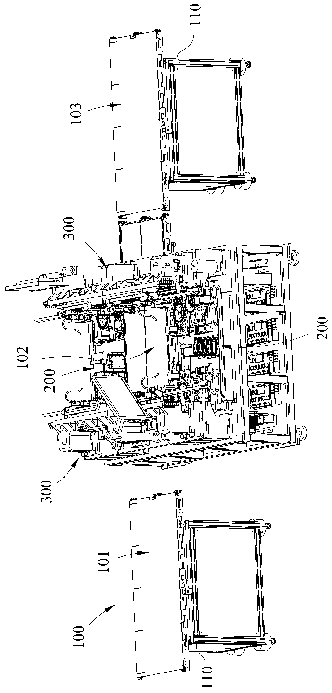
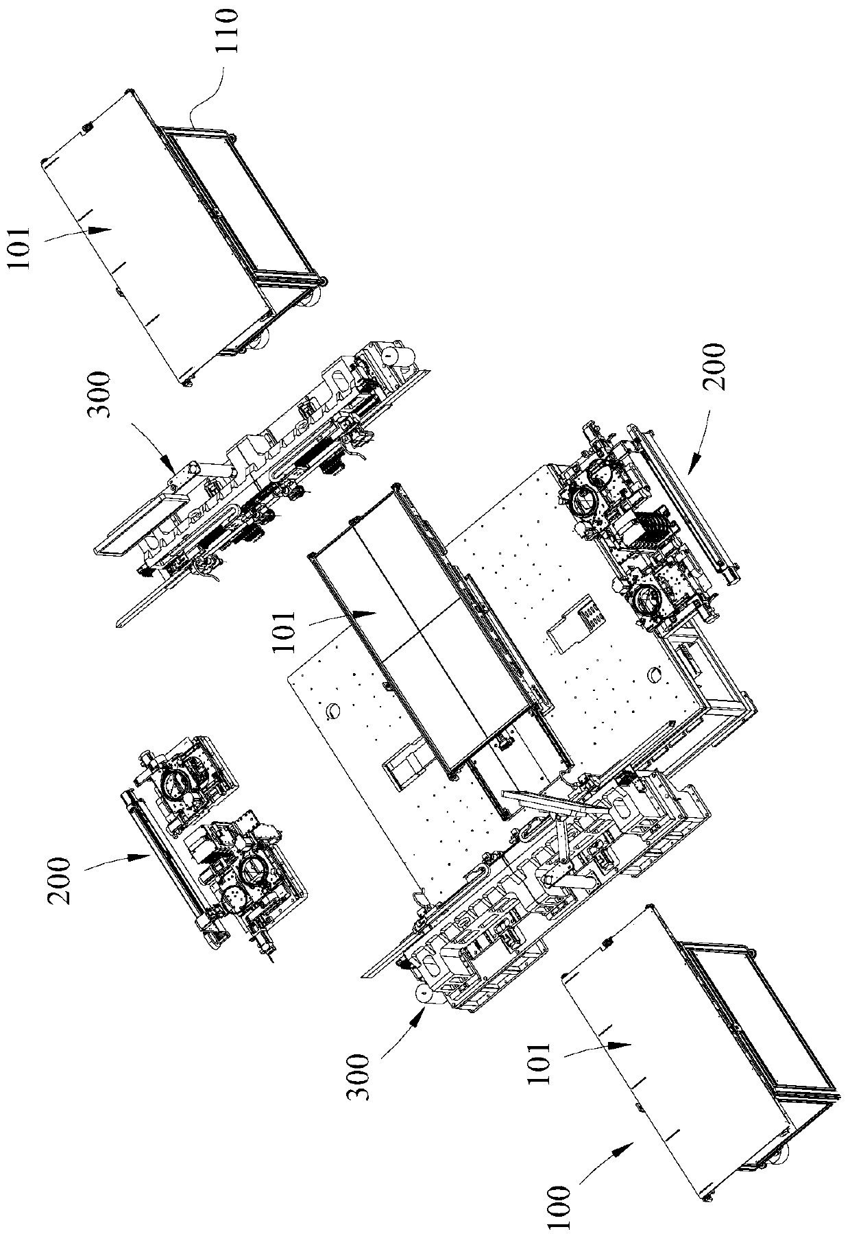
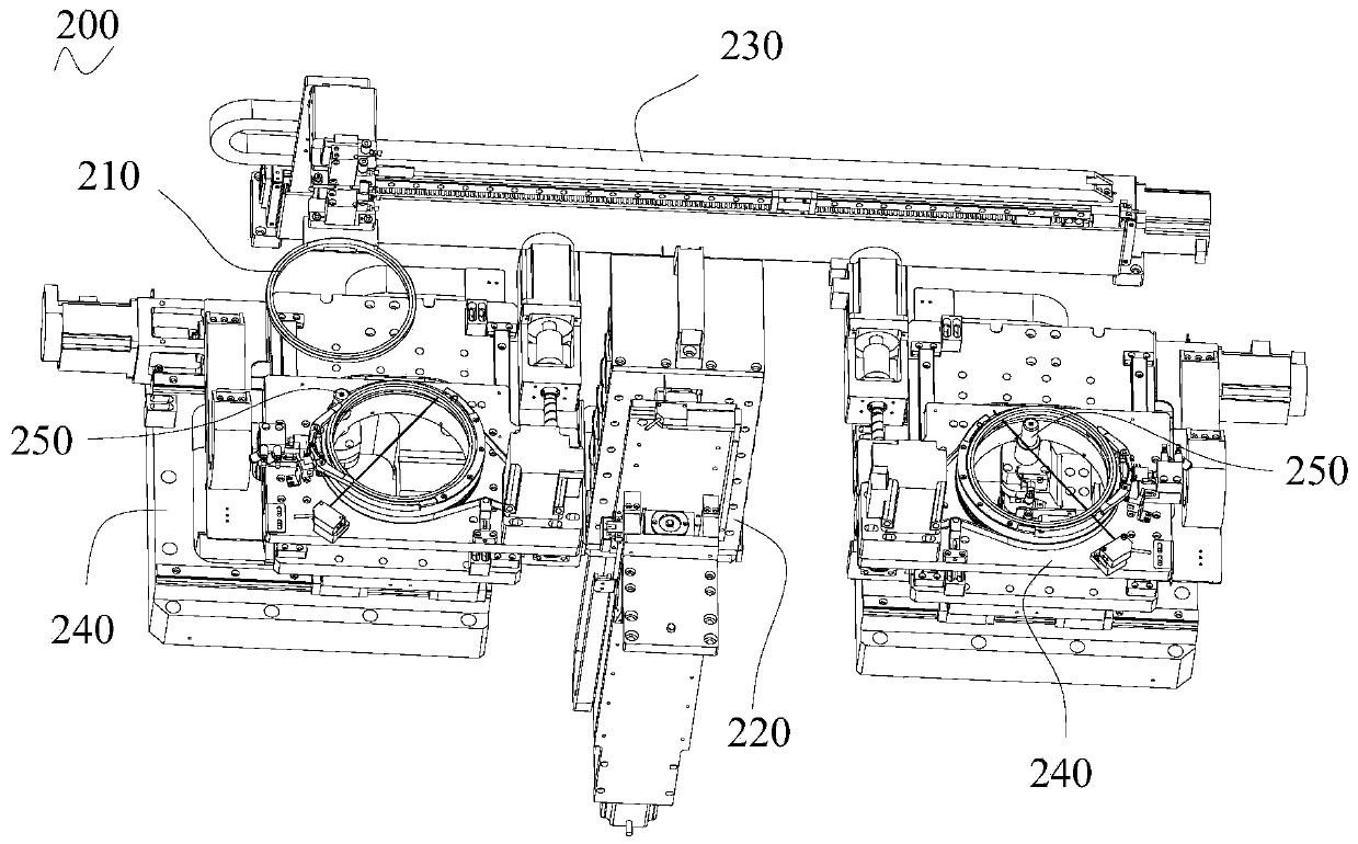
[0027] see Figure 1 to Figure 5 , the die-bonding equipment includes:

[0028] The transfer device (100) is used to drive the substrate to move from front to back, and sequentially pass through the board entry station 101, the solid crystal station 102, and the board exit station 103;

[0029] The feeding device 200 is used to supply wafers, including a crystal ring 210, a crystal ring storage assembly 220, a crystal ring moving assembly 230, a crystal frame moving assembly 240 and a thimble assembly 250, and the ...


PUM


Abstract

The invention relates to the technical field of automatic equipment, in particular to die bonding equipment, which comprises a conveying device used for driving a substrate to move from front to backand sequentially pass through a substrate feeding station, a die bonding station and a substrate discharging station; a feeding device used for supplying wafers; and at least two die bonding devices,wherein the die bonding devices are oppositely arranged in the front-back direction, and are arranged at a die bonding station, and each die bonding device comprises at least two die bonding units, the die bonding units obtaining wafers from the feeding device and fixing the wafers to different areas of the substrate for die bonding. Each die bonding unit comprises a bonding head mechanism and a displacement driving mechanism connected with the bonding head mechanism, wherein the bonding head mechanism can grab a plurality of wafers at the feeding device and fix the wafers at the die bonding station, and the displacement driving mechanism is used for driving the bonding head mechanism to reciprocate between the feeding device and the die bonding station. According to the invention, the moving range of the die bonding units is reduced, so that the displacement deviation of the die bonding units can be reduced, and the die bonding precision is improved.

Description

technical field [0001] The invention relates to the technical field of automation equipment, in particular to a crystal bonding equipment. Background technique [0002] Die-bonding equipment is a device that can fix LED chips on LED brackets. The existing fixing equipment is only suitable for small-sized LED brackets, not for large-sized LED brackets. Specifically, if the existing crystal-bonding equipment is directly used to fix the crystal on the large-sized LED bracket, it is necessary to expand the crystal-bonding unit (310)( That is, directly obtain the LED chip from the feeding device (200) and fix the LED chip to the structural part of the LED bracket) travel range, and expand the travel range of the die-bonding unit (310), which will increase the displacement of the die-bonding unit (310) Deviation, resulting in poor die bonding accuracy. Contents of the invention [0003] The object of the present invention is to overcome the shortcomings of the above-mentioned ...

Claims


Application Information

Patent Timeline
IPC IPC(8): H01L33/48H01L21/67
CPCH01L21/67092H01L33/48
Inventor 胡新荣
Owner 中山市新益昌自动化设备有限公司
Learn More