Check patentability & draft patents in minutes with Patsnap Eureka AI!

Direct-current circuit breaker transfer branch unit based on IEGT

A DC circuit breaker and transfer branch technology, applied in electrical components, emergency protection circuit devices, etc., can solve the problems of inconvenient maintenance and large valve group size, achieve easy installation and maintenance, ensure uniform distribution, and neutralize improved effect

Pending Publication Date: 2020-08-25
CHANGZHOU BORI ELECTRIC POWER AUTOMATION EQUIP +2
View PDF0 Cites 1 Cited by
  • Summary
  • Abstract
  • Description
  • Claims
  • Application Information

AI Technical Summary

Problems solved by technology

[0004] In order to solve the deficiencies in the prior art, the present invention provides an IEGT-based transfer branch unit of a DC circuit breaker, which solves the problems of separate arrangement of each valve group in the transfer branch unit used in the existing DC circuit breaker, large valve group volume, The problem of inconvenient maintenance

Method used


Image

  • Direct-current circuit breaker transfer branch unit based on IEGT
  • Direct-current circuit breaker transfer branch unit based on IEGT
  • Direct-current circuit breaker transfer branch unit based on IEGT

Examples


Embodiment 1

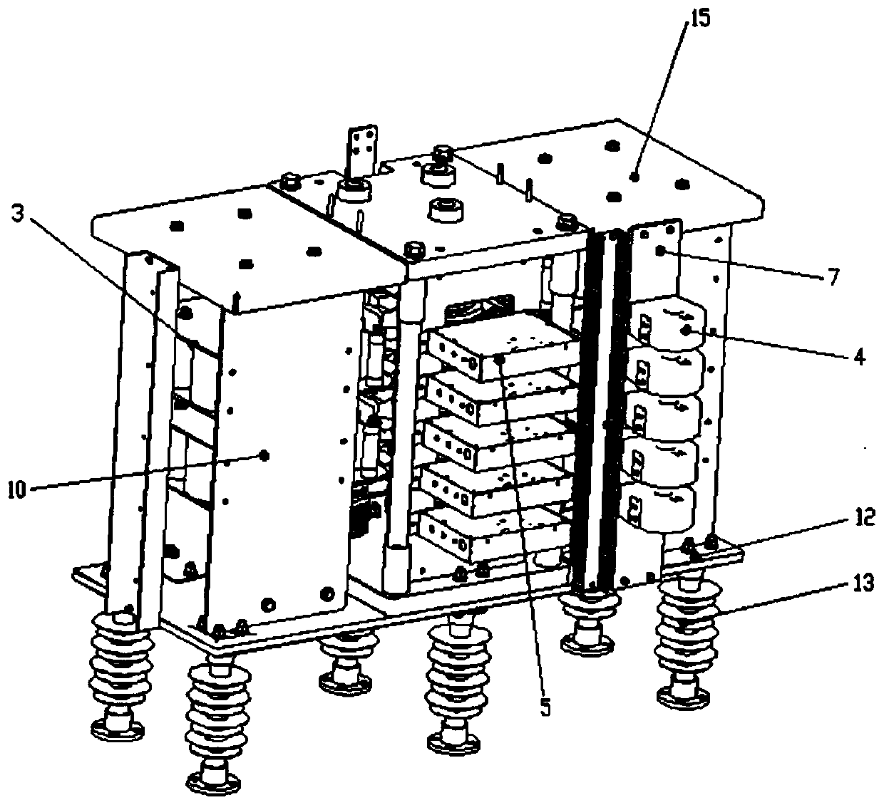
[0029] Such as figure 1 As shown, a DC circuit breaker transfer branch unit based on IEGT includes a valve string crimping mechanism, a plurality of RCM buffer energy consumption units 3 respectively connected to the IEGT devices in the valve string crimping mechanism, and a valve string crimping A plurality of driving boards 5 connected to the IEGT devices in the mechanism and a plurality of energy supply coils 4 respectively connected to the driving boards;

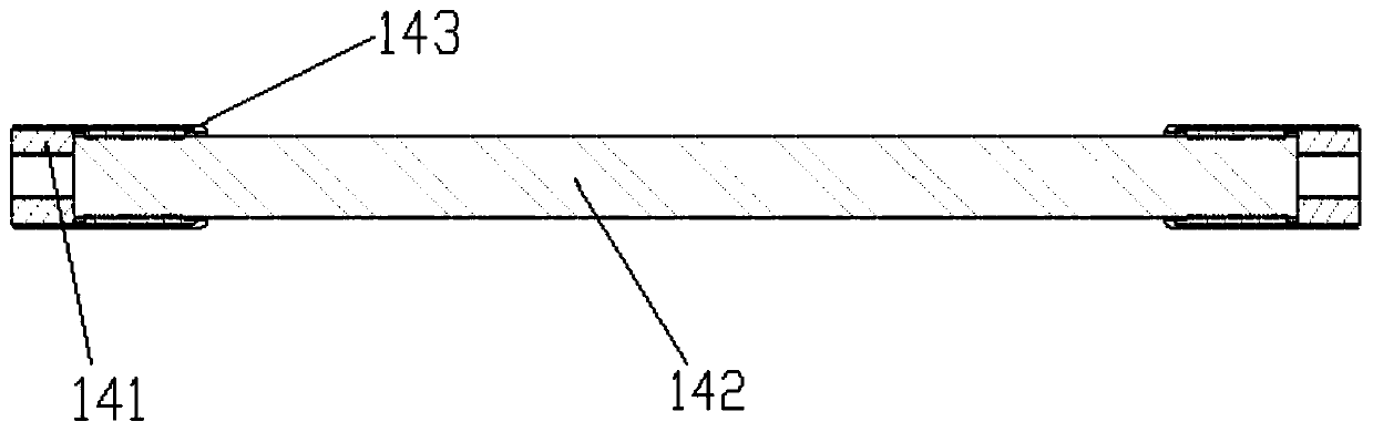
[0030] Such as figure 2 As shown, the valve string crimping mechanism includes: a first pressing plate 6, a second pressing plate, an insulating pull rod, and at least one group of three series valves fixed between the first and second pressing plates (to realize the two-way flow of current ), the insulating pull rod is fixed between the first compression plate 6 and the second compression plate, and the first and second compression plates and the insulating pull rod form a cage frame; further, there are four insulati...

Embodiment 2

[0047] The difference from Embodiment 1 is that the valve string crimping mechanism includes: a first compression plate 6, a second compression plate, an insulating pull rod, and at least one IEGT fixed between the first and second compression plates The crimping unit can realize unidirectional current flow.

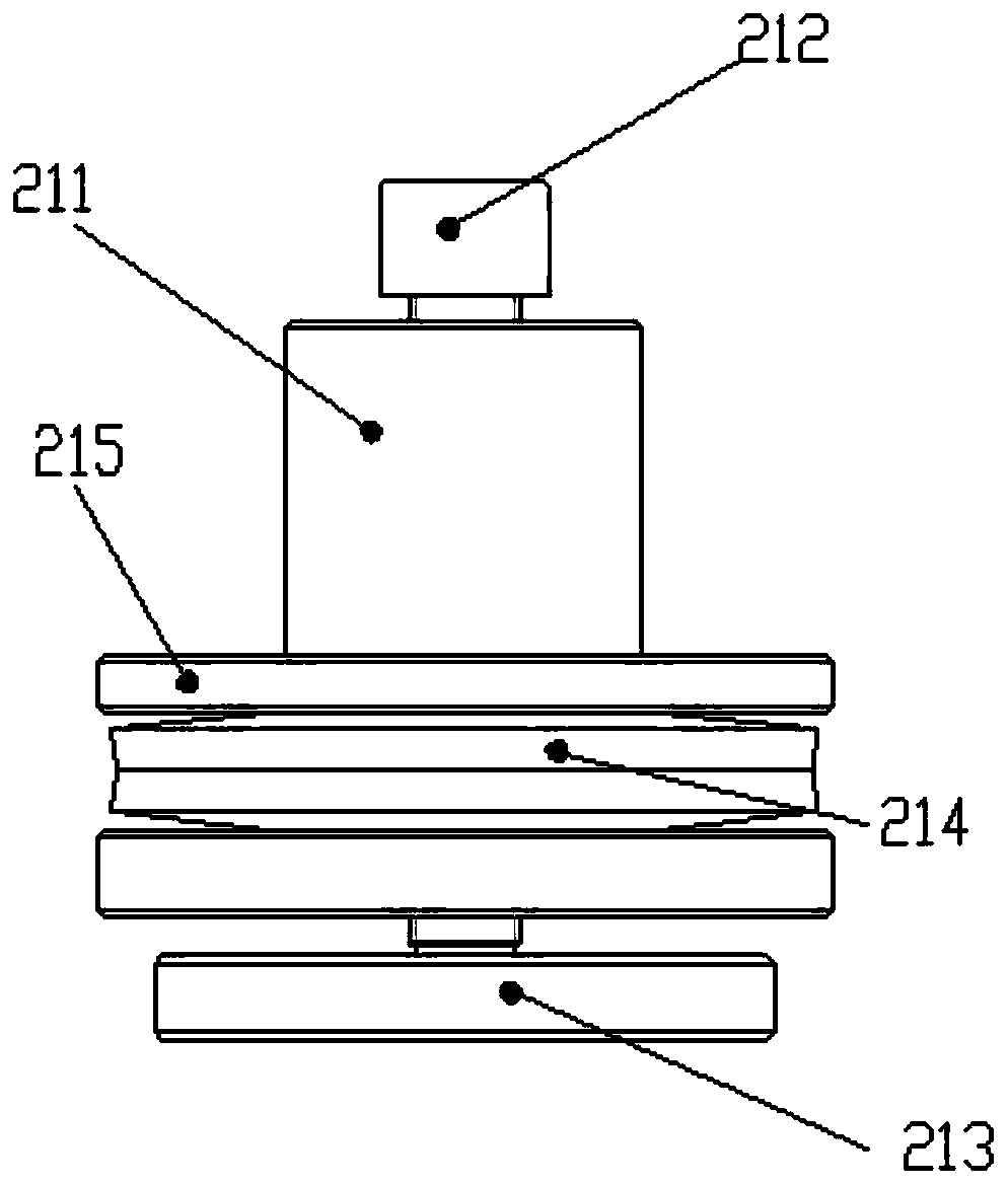
[0048] The specific method of use is: use a torque wrench to tighten the ball stud bolt 212 to generate pressure on the ball socket pressing plate 213, and the press-fitting structure moves up to the disc spring upper plate 215 to contact the first pressing plate 6 to form a limit, and the disc spring upper plate Under the limit action of 215, after the disk spring 214 is compressed by force, the pressure is transmitted to the IEGT device through the ball stud 212, the ball socket pressure plate 213, and the insulating pad, so that the entire crimping unit can be crimped. According to the pressure value of the device The requirement is converted into the torque value of ...


PUM


Abstract

The invention discloses a direct-current circuit breaker transfer branch unit based on an IEGT, which comprises a valve string crimping mechanism, a plurality of RCM buffer energy consumption units connected in parallel with a plurality of IEGT devices in the valve string crimping mechanism respectively, a plurality of driving board cards connected with the plurality of IEGT devices in the valve string crimping mechanism respectively, and a plurality of energy supply coils connected with the driving board cards respectively. The valve string crimping mechanism comprises a first pressing plate,a second pressing plate, an insulating pull rod and at least one group of three-string valves or at least one IEGT crimping unit fixed between the first pressing plate and the second pressing plate,the insulating pull rod is fixed between the first pressing plate and the second pressing plate; the three-string valve comprises an IEGT crimping unit and two diode crimping units. The structure is more compact and modularized, the occupied space is saved, the overall size is reduced, and installation and maintenance in the cabinet type direct-current circuit breaker are facilitated.

Description

technical field [0001] The invention relates to the technical field of direct current transmission, in particular to an IEGT-based transfer branch unit of a direct current circuit breaker. Background technique [0002] With the development of DC distribution network, the application of DC circuit breaker in distribution network is one of the key equipment to ensure the stable operation of the power grid. When a fault occurs, it is necessary to shut down the entire multi-terminal DC system for a short time to clear the fault, and then restart the DC system. The DC circuit breaker can quickly, reliably and selectively remove the fault point, and it can still ensure that when a certain line fails Other lines run stably to maintain the safe and stable operation of the DC power grid and protect key equipment in the power grid. Among them, as a transfer branch unit for fault clearing after current conversion, it is generally realized by using a power electronic switching valve. ...

Claims


Application Information

Patent Timeline
Patent Type & Authority Applications(China)
IPC IPC(8): H02H7/26
CPCH02H7/268
Inventor 李德召姚宁李骏杜道忠王智勇王文杰杨兵
Owner CHANGZHOU BORI ELECTRIC POWER AUTOMATION EQUIP
Features
  • R&D
  • Intellectual Property
  • Life Sciences
  • Materials
  • Tech Scout
  • Unparalleled Data Quality
  • Higher Quality Content
  • 60% Fewer Hallucinations
Learn More