Granulated feed conveying device

A technology of conveying device and pellet feed, which is applied in conveyors, transportation and packaging, loading/unloading, etc., can solve the problems of increased energy consumption of equipment by throwing force, scattered distance of dust-prone materials, and time-consuming cleaning, etc., and achieves high flexibility. , to avoid the effect of throwing force and energy consumption

Inactive Publication Date: 2020-08-28
胡艳锋
View PDF11 Cites 0 Cited by
  • Summary
  • Abstract
  • Description
  • Claims
  • Application Information

AI Technical Summary

Problems solved by technology

[0004] The main purpose of the present invention is to overcome the deficiencies of the prior art, to provide a pellet feed conveying device, to solve the problem that the vertical screw conveyor adopts vertical feeding and high-level blanking to realize feeding and discharging, and the rotating force of the screw rod when discharging. The material is driven to be discharged in a rotating manner, which is easy to raise dust and the material is scattered over a wide distance. It is time-consuming to clean up, and the force generated by the spiral blanking increases the energy consumption of the equipment.

Method used


Image

  • Granulated feed conveying device
  • Granulated feed conveying device
  • Granulated feed conveying device

Examples


Embodiment 1

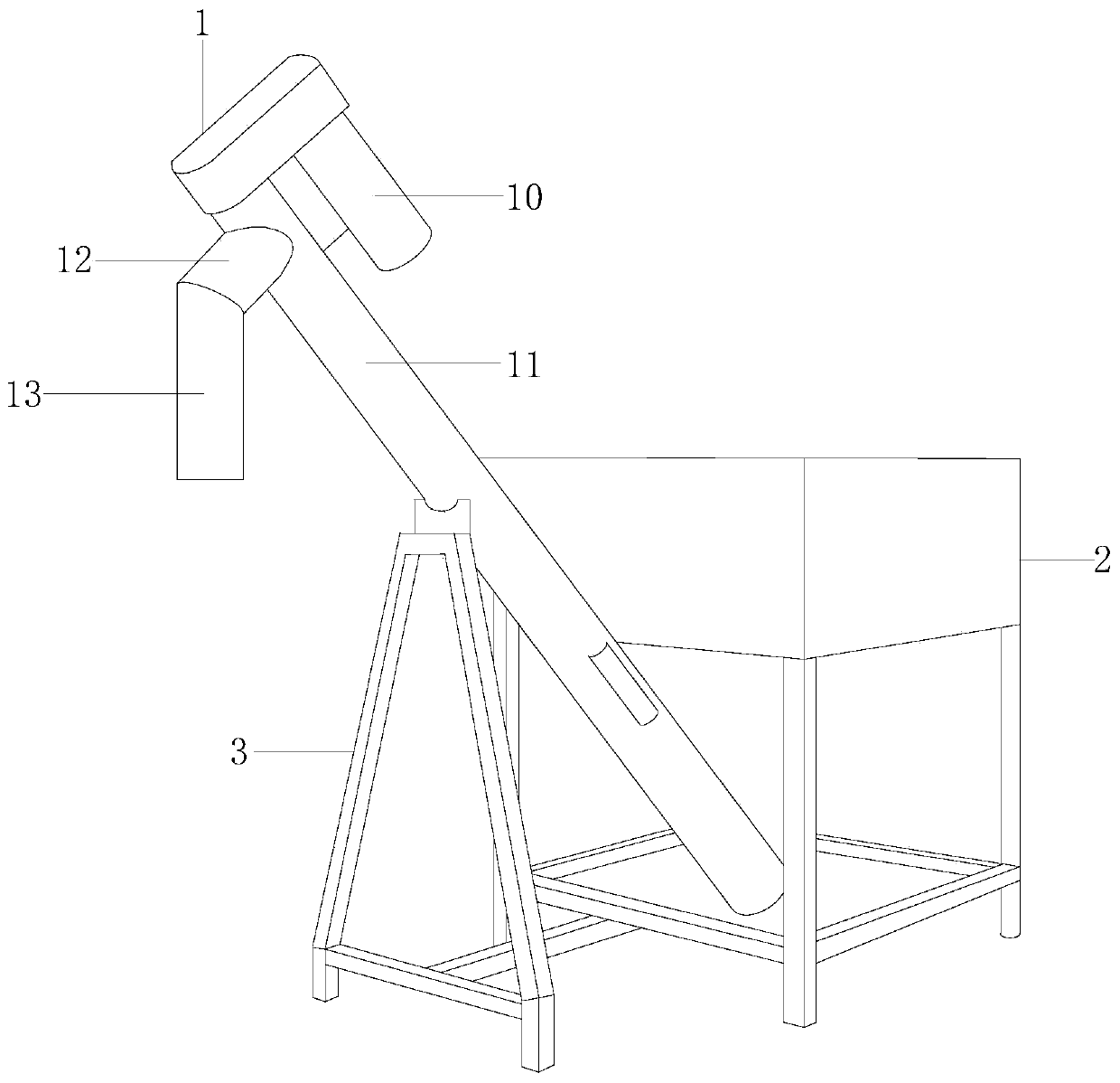
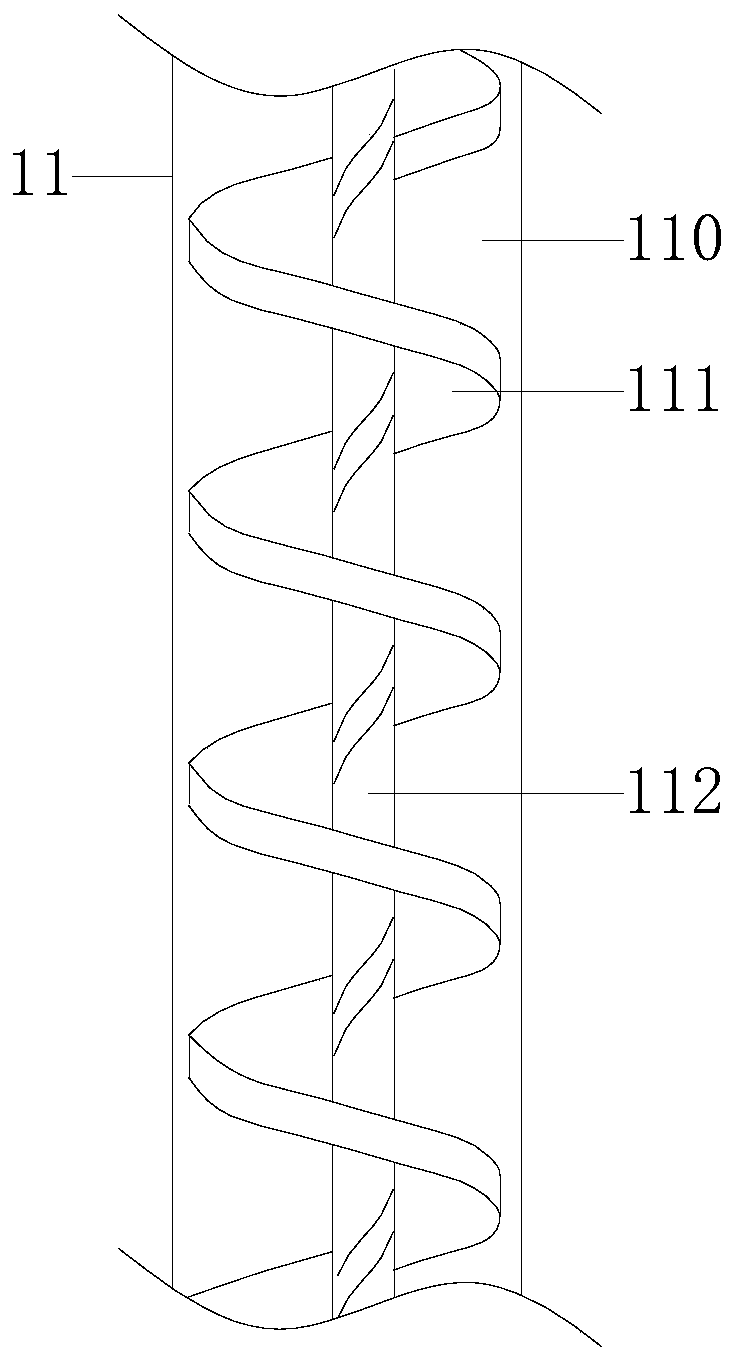
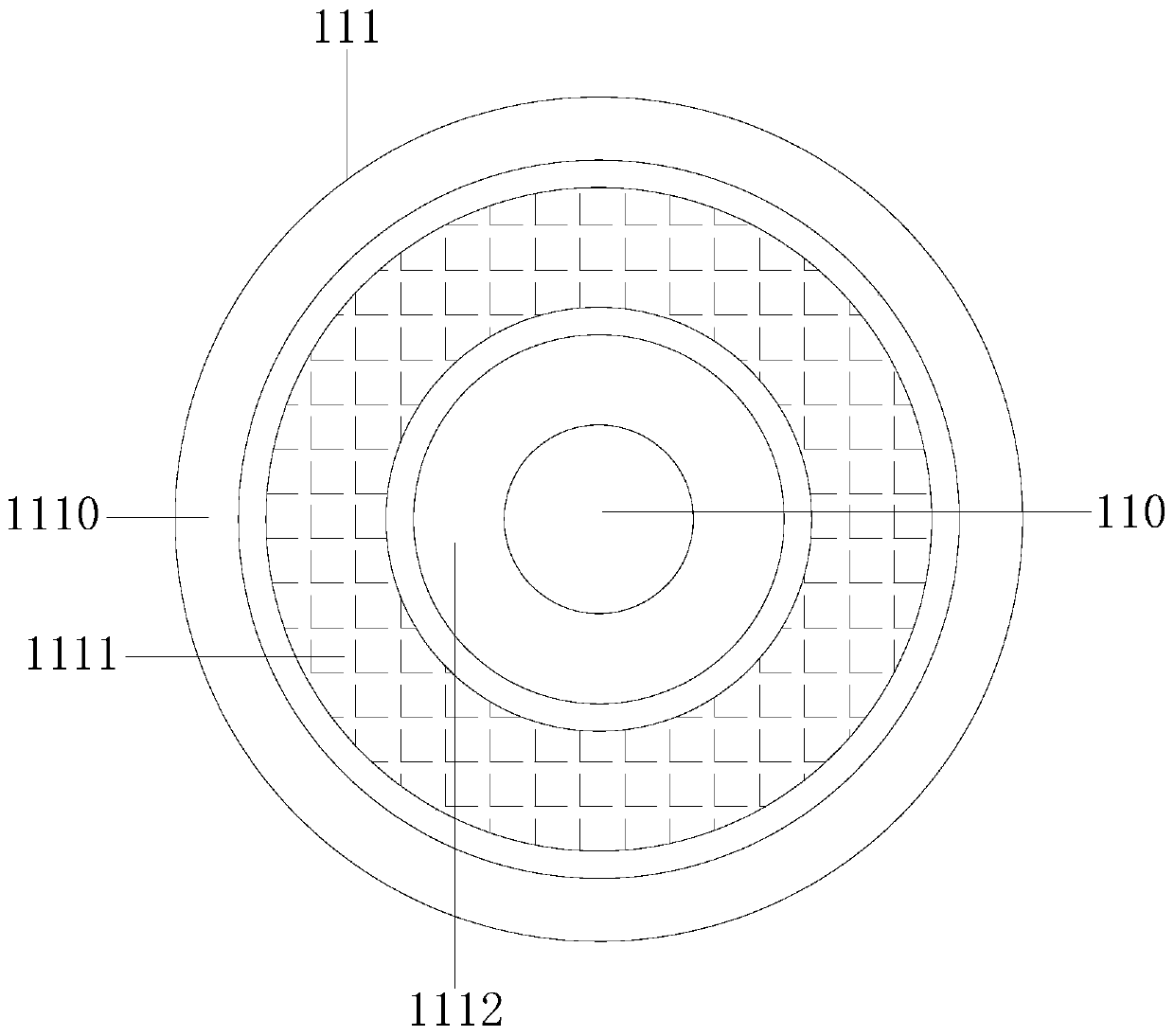
[0026] Example 1 see Figure 1-5 , the present invention provides a technical solution for a granular feed conveying device: its structure includes a feeding structure 1, a charging frame 2, and a support frame 3, the right end of the feeding structure 1 is installed and connected to the charging frame 2, and the charging frame 2. The left end is welded with the support frame 3, and the conveying structure 1 is arranged on the upper end of the support frame 3. The conveying structure 1 is composed of a motor 10, a conveying cylinder 11, a rotating material cylinder 12, and a blanking cylinder 13. The motor 10 It is installed and connected with the upper end of the conveying cylinder 11. The left and right ends of the rotating material cylinder 12 are welded with the conveying cylinder 11 and the blanking cylinder 13. The conveying cylinder 11 includes a conveying cylinder body 110, a conveying screw 111, and a conveying shaft 112. The conveying screw 111 and the conveying shaf...

Embodiment 2

[0028] Example 2 see Figure 6 , 7, the present invention provides a technical solution for a granular feed conveying device: the structure of the blanking cylinder 13 includes a thread groove 130, a lifter 131, a blanking cylinder body 132, and a turning structure 133, and the inner ring of the blanking cylinder body 132 There is a thread groove 130 on the side, and the thread groove 130 plays the role of material buffering. The lifter 131 is installed on the blanking barrel body 132 and the two form an integrated structure. The lifter 131 is used to adjust the drop. The height of the barrel 13 improves the flexibility of discharging. The bottom of the blanking barrel body 132 is installed and connected with the turning structure 133. The turning structure 133 includes a blanking tray 1330 and a main body turning tray 1331. The blanking tray 1330 is installed and connected to the upper end of the main body turning plate 1331, the blanking plate 1330 is embedded with a blanki...


PUM


Abstract

The invention discloses a granulated feed conveying device. The conveying device structurally comprises a conveying structure, a loading frame and a supporting frame, the conveying structure and the loading frame are in mounting connection, the loading frame and the supporting frame are welded, the conveying structure is mounted on the supporting frame, the conveying structure is composed of a motor, a conveying cylinder, a transferring cylinder and a falling cylinder, the motor and the conveying cylinder are in mounting connection, the transferring cylinder is welded with the conveying cylinder and the falling cylinder, the conveying cylinder comprises a conveying cylinder body, a conveying spiral rod, and a conveying shaft rod, the conveying spiral rod is welded with the conveying shaftrod, the conveying spiral rod and the conveying shaft rod are mounted in the conveying cylinder body, the conveying spiral rod comprises a spiral outer groove position, a spiral middle groove position, and a spiral inner groove position, the conveying spiral rod achieves particle and dust separated conveying, materials are collected into stacked materials to avoid raised dust, during discharging,a falling disc accumulates materials, a main turnover disc turns over for falling, discharging is in order, scattering is avoided, a discharging opening is adjustable in lifting, flexibility is high,vertical falling is carried out, and force throwing energy consumption is avoided.

Description

technical field [0001] The invention relates to the technical field of conveying pipelines for pellet feed, in particular to a pellet feed conveying device. Background technique [0002] Pellet feed conveying equipment can reduce the labor intensity of transportation and improve work efficiency. Vertical screw conveyor is a kind of pellet feed conveying equipment. It is used in places with limited feeding space. Various powder pellets can reach short distance A type of conveying machinery that lifts vertically. [0003] The prior art vertical screw conveyor adopts vertical feeding and high-level blanking to realize feeding and discharging. When discharging, the rotating force of the screw rod drives the material to be discharged in a rotating manner. It is time-consuming, and the throwing force generated by the spiral blanking increases the energy consumption of the equipment. Contents of the invention [0004] The main purpose of the present invention is to overcome the...

Claims


Application Information

Patent Timeline
Patent Type & Authority Applications(China)
IPC IPC(8): B65G65/46B65G69/18
CPCB65G65/46B65G69/186B65G2201/04
Inventor 胡艳锋
Owner 胡艳锋
Why Eureka
Try Eureka