
Dual-ball lead screw lifting mechanism

A technology of lifting mechanism and ball screw, which is applied in the direction of lifting frame, lifting device, casting and molding equipment, etc., which can solve the problems of inconvenient printing table overall movement, long screw rod, and large occupied volume.

Pending Publication Date: 2020-08-28
佛山市晗宇科技有限公司
View PDF1 Cites 1 Cited by
  • Summary
  • Abstract
  • Description
  • Claims
  • Application Information

AI Technical Summary

Problems solved by technology

Patent CN208916730U discloses a lifting platform for 3D printing equipment, which realizes the lifting of the lifting platform through a ball screw mechanism, and has high precision; however, such a lifting mechanism has a relatively small lifting stroke. The length of the rod needs to be set to be longer, occupying a larger volume, and the height of the zero position is higher, which is not convenient for the overall movement of the printing table

Method used


Image

  • Dual-ball lead screw lifting mechanism
  • Dual-ball lead screw lifting mechanism
  • Dual-ball lead screw lifting mechanism

Examples


Embodiment Construction

[0021] Embodiments of the present invention are described in detail below, examples of which are shown in the drawings, wherein the same or similar reference numerals designate the same or similar elements or elements having the same or similar functions throughout. The embodiments described below by referring to the figures are exemplary only for explaining the present invention and should not be construed as limiting the present invention.

[0022] In the description of the present invention, it should be understood that the orientation descriptions, such as up, down, front, back, left, right, etc. indicated orientations or positional relationships are based on the orientations or positional relationships shown in the drawings, and are only In order to facilitate the description of the present invention and simplify the description, it does not indicate or imply that the device or element referred to must have a specific orientation, be constructed and operated in a specific ...


PUM


Abstract

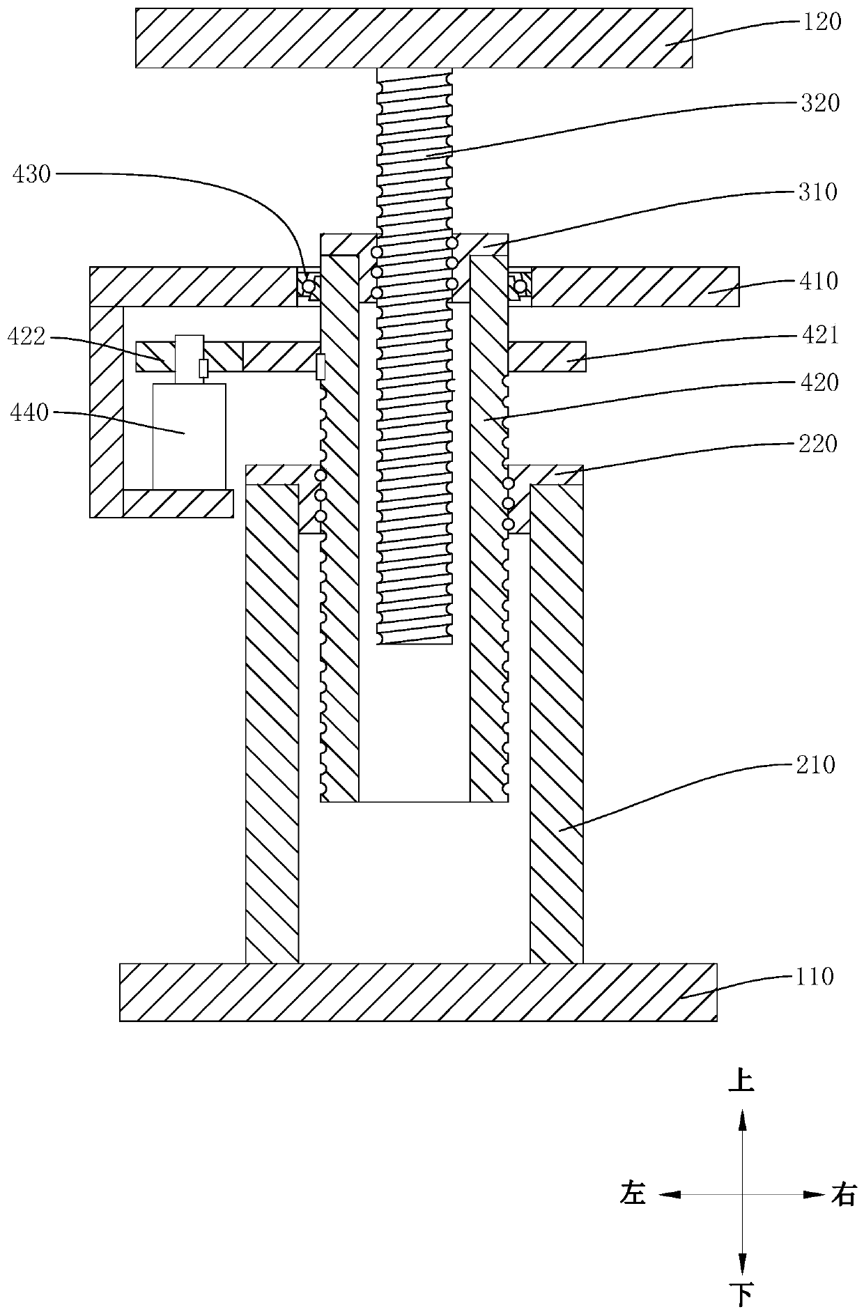
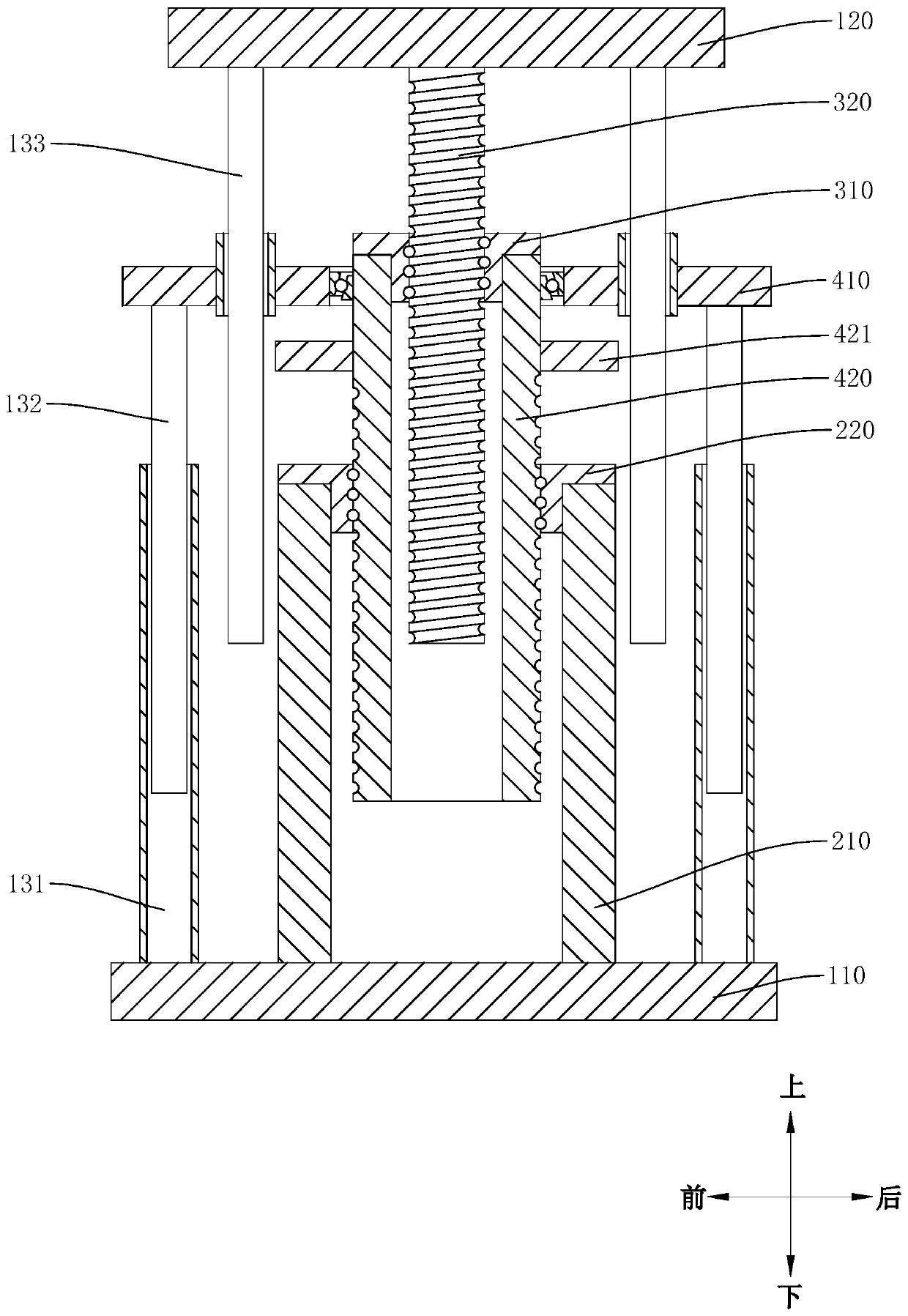
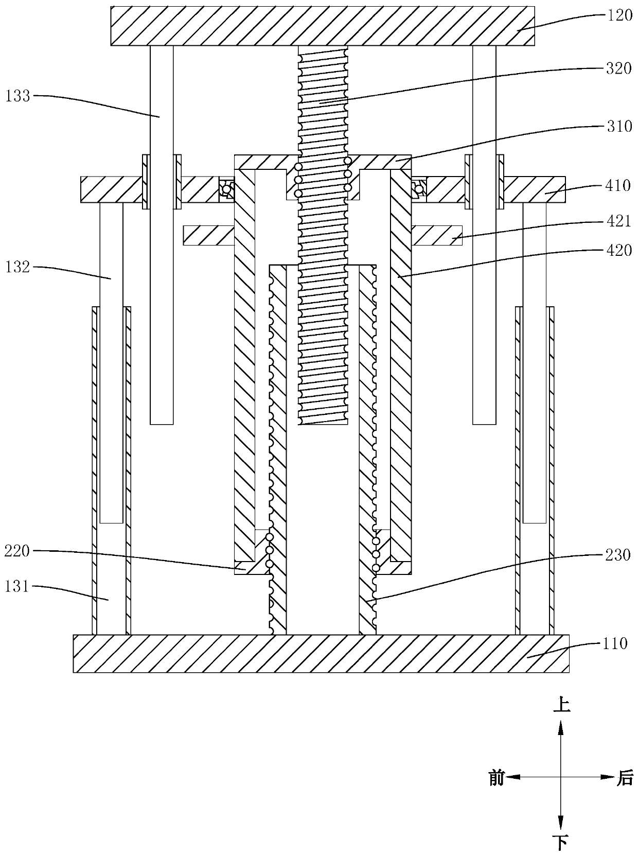
The invention discloses a dual-ball lead screw lifting mechanism. The dual-ball lead screw lifting mechanism comprises a connecting assembly, a first ball lead screw assembly, a second ball lead screwassembly and a base, wherein the connecting assembly comprises a lifting base and a first rotary shaft; the first rotary shaft is rotatably connected to the lifting base; a rotary driver is arrangedon the lifting base; the first ball lead screw assembly comprises a first lead screw and a first ball nut; the first rotary shaft sleeves outside the first lead screw; the second ball lead screw assembly comprises a second lead screw and a second ball nut; the second lead screw and the first lead screw are reverse in rotation directions; the second lead screw sleeves outside the first lead screw;a second tube body is fixedly arranged on the second ball nut; the second tube body sleeves outside the second lead screw; and the first lead screw is fixedly arranged on the base or one of the secondtube body and the second lead screw is fixedly arranged on the base. While the rotary driver drives the first rotary shaft to rotate, the first lead screw and an external connector can get away fromthe lifting base or get close to the lifting base simultaneously; and a lifting platform is arranged on one of the first lead screw and the external connector, and the other one is fixedly arranged onthe base, so that the lifting stroke of the lifting platform is greater.

Description

technical field [0001] The invention relates to the technical field of transmission devices, in particular to a double ball screw lifting mechanism. Background technique [0002] In existing 3D printers, the printing head usually moves along the X-axis and the Y-axis, and the middle part of the printing table is provided with a lifting platform that can move along the Z-axis, so that the printing head can make a three-dimensional position change relative to the lifting platform. [0003] For a 3D printer whose printing target is a workpiece with a large volume and mass, such as a 3D printer for making sand molds, it is difficult to take out the sand mold after printing, so the printing table needs to be able to move to the outside of the 3D printer as a whole. Patent CN208916730U discloses a lifting platform for 3D printing equipment, which realizes the lifting of the lifting platform through a ball screw mechanism, and has high precision; however, such a lifting mechanism h...

Claims


Application Information

Patent Timeline
IPC IPC(8): B66F7/14B66F7/28B22C9/02B33Y30/00
CPCB66F7/14B66F7/28B22C9/02B33Y30/00
Inventor 韩聪李亦农袁纯国黄慧宇
Owner 佛山市晗宇科技有限公司
Features
  • Generate Ideas
  • Intellectual Property
  • Life Sciences
  • Materials
  • Tech Scout
  • Unparalleled Data Quality
  • Higher Quality Content
  • 60% Fewer Hallucinations
Learn More