Disc single-shot detonator explosive pressing device and using method thereof
A detonator and charge-pressing technology, which is applied in the field of disc single-shot detonator charge-pressing devices, can solve problems such as uneven pressure on the detonator, poor quality homogeneity of the detonator, affecting precision and controlling the quality of the blasting project, and achieves pressure reduction, Increased productivity, precise pressure and constant results
- Summary
- Abstract
- Description
- Claims
- Application Information
AI Technical Summary
Problems solved by technology
Method used
Image
Examples
Embodiment 1
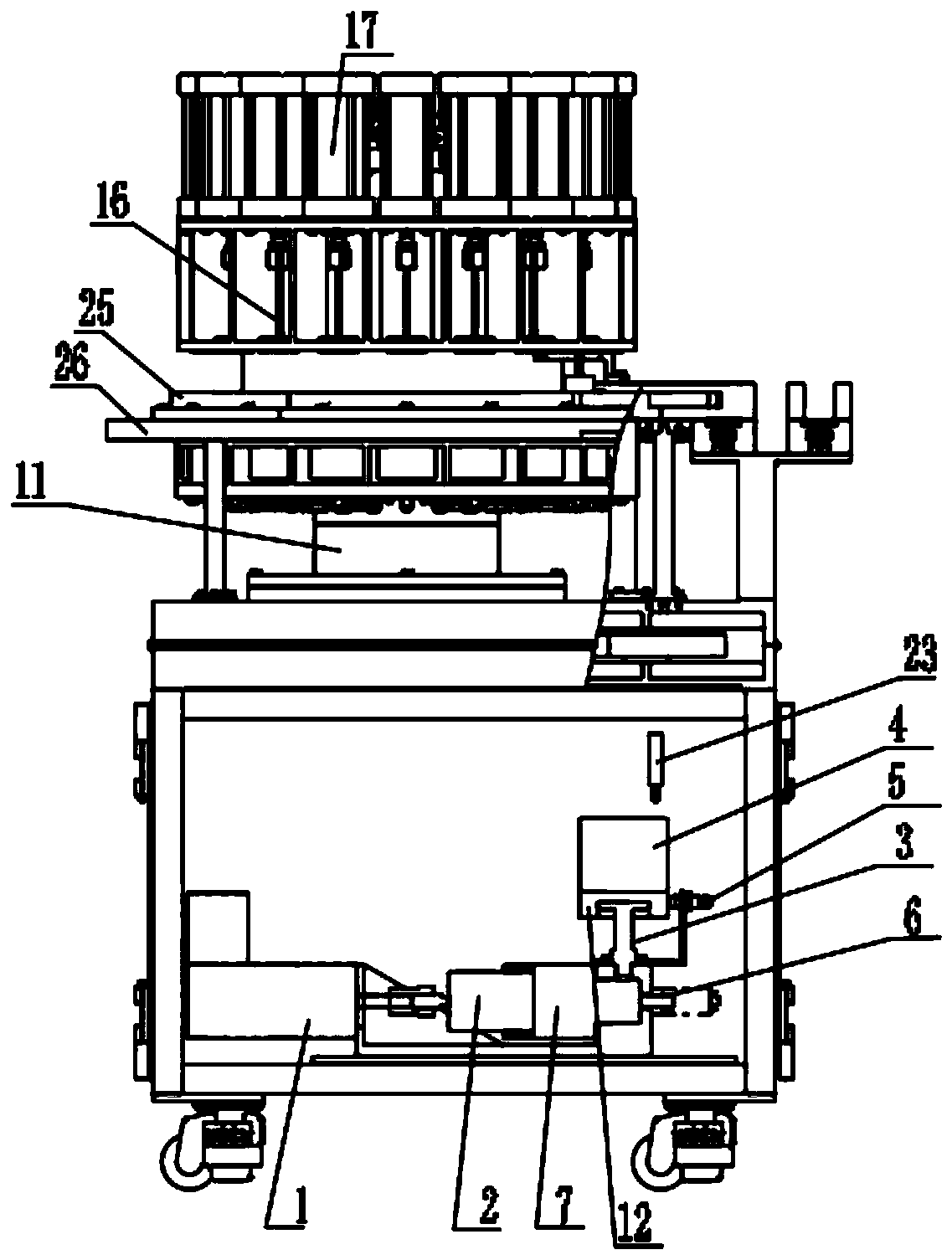
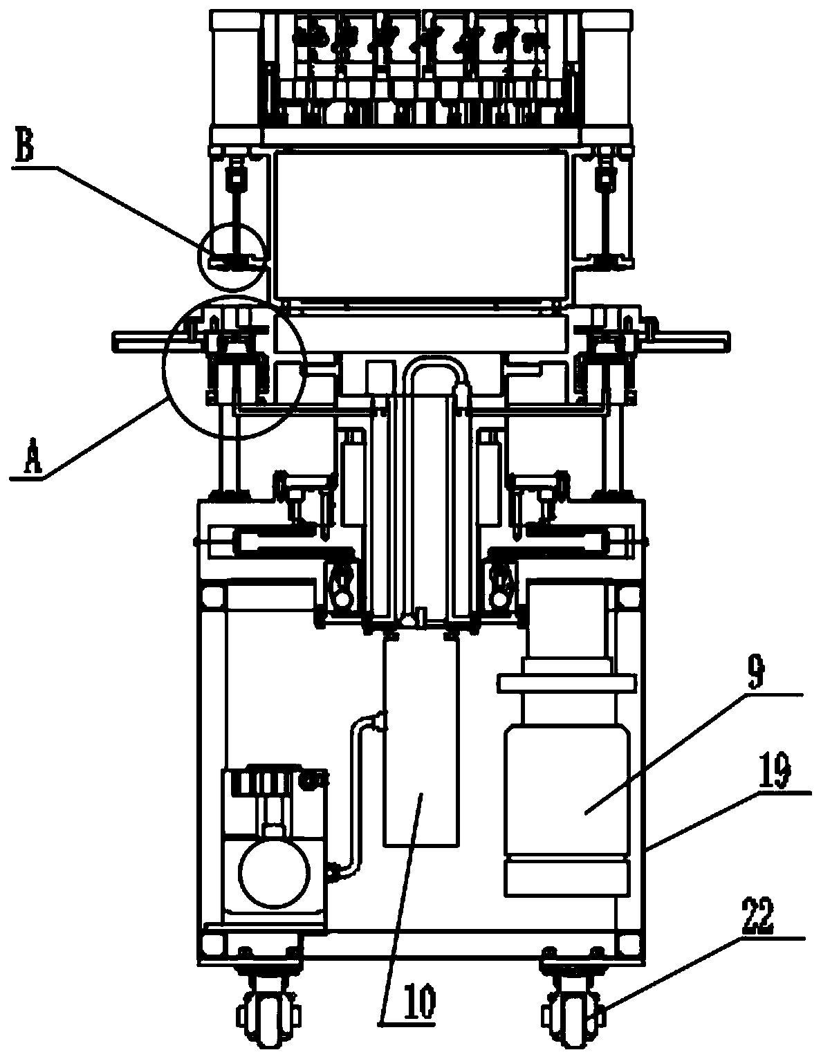
[0033] like Figure 1~4 As shown, a disc single-shot detonator pressure device shown in a preferred embodiment of the present invention includes a central rotating table 11 and a power assembly 9, and the central rotating table 11 is connected to the power assembly 9, and the power assembly 9 can be The rotation of the central rotating table 11 provides power. In this embodiment, the power assembly 9 mainly adopts a motor, and a gear is connected to the output end of the motor. This gear meshes with the central gear of the central rotating table 11. The large gear rotates, thereby driving the central rotary table 11 to rotate, and the top of the central rotary table 11 is provided with a mold running platform 18, and the mold running platform 18 includes a rotating part 25 and a fixed part 26, and the rotating part 25 is located at the fixed part The center of 26 is fixedly connected with the central rotary table 11, and can rotate with the rotation of the central rotary table...
Embodiment 2
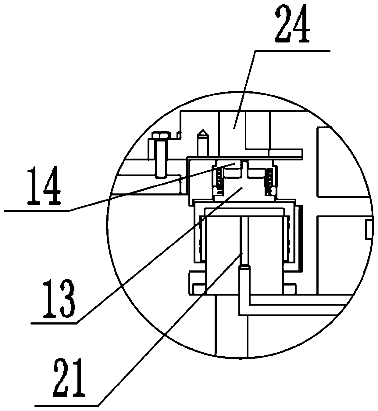
[0041] On the basis of Embodiment 1, a support column 14 is provided below the mold placement groove 24, and a hydraulic jack 13 is connected to the bottom of the support column 14, and a hydraulic compensation system is connected to the hydraulic jack 13. The hydraulic compensation system can accurately control the pressure on the detonator on the support mold column 14 to a constant value, so that the pressure value on the explosive column in each detonator is accurate and consistent.
[0042] Specifically, the hydraulic compensation system includes an electric cylinder 1, an adjusting plunger 2, a hydraulic container 7, a piston pressure gauge 3 and a weight 4. One end of the adjusting plunger 2 is connected to the electric cylinder 1 and the other end is connected to the hydraulic container 7. , the piston pressure gauge 3 is connected with the hydraulic container 7, the standard plunger of the piston pressure gauge 3 is fixedly connected with the connecting seat 12, the we...
Embodiment 3
[0045] On the basis of Embodiment 2, the hydraulic compensation system further includes a displacement sensor 23 , and the displacement sensor 23 is located above the weight 4 . When the displacement sensor 23 detects a small change in the rise or fall of the weight 4, it will send a signal to the servo system to drive the electric cylinder 1, and the electric cylinder 1 drives the adjustment plunger 2 to retreat or advance, so that the piston pressure gauge 3 and the weight 4 It can only move up and down within a very small range of motion, ensuring that the piston pressure gauge 3 works within the effective range, further ensuring the stability of the entire hydraulic compensation system, and the connection and drive relationship between the servo system, the displacement sensor 23 and the electric cylinder 1 It is a prior art, not an innovative point of the present invention, and will not be repeated here.
[0046] Preferably, the hydraulic compensation system further inclu...
PUM
 Abstract
Description
Claims
Application Information
 - R&D
- Intellectual Property
- Life Sciences
- Materials
- Tech Scout
- Unparalleled Data Quality
- Higher Quality Content
- 60% Fewer Hallucinations
Browse by: Latest US Patents, China's latest patents, Technical Efficacy Thesaurus, Application Domain, Technology Topic, Popular Technical Reports.
© 2025 PatSnap. All rights reserved.Legal|Privacy policy|Modern Slavery Act Transparency Statement|Sitemap|About US| Contact US: help@patsnap.com


