Mapping equipment, installing method and key structure for mapping equipment installation

A technology for equipment installation and equipment, which is applied to mechanical equipment, valve devices, connecting components, etc., and can solve the problems of difficult installation, difficult alignment of installation holes and installation points, etc.

Active Publication Date: 2020-08-28
XIANGTAN UNIV
View PDF8 Cites 0 Cited by
  • Summary
  • Abstract
  • Description
  • Claims
  • Application Information

AI Technical Summary

Problems solved by technology

[0002] When a conventional surveying instrument is assembled with its triangle three, it is necessary to align the installation hole of the surveying instrument with the installation point first, and then carry out the assembly work. Since the installation hole and the installation point are more difficult to align, resulting in more difficult installation, so urgently There is a need for a solution that can alleviate the above problems

Method used


Image

  • Mapping equipment, installing method and key structure for mapping equipment installation
  • Mapping equipment, installing method and key structure for mapping equipment installation
  • Mapping equipment, installing method and key structure for mapping equipment installation

Examples


Embodiment 1

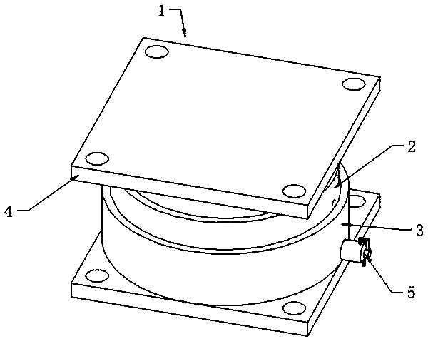
[0025] see Figure 1-3 , an embodiment provided by the present invention: a surveying and mapping equipment, including an installation docking structure 1; the installation docking structure 1 includes an exhaust main body 2, a fixed seat 3, a docking seat 4 and a suction cup main body 5, and the lower end of the docking seat 4 is adsorbed and fixed On the upper end of the exhaust main body 2, the lower end of the exhaust main body 2 is slidably installed on the upper end of the fixed seat 3, the exhaust main body 2 is adsorbed and fixed by the fixed seat 3, and the suction cup main body 5 is fixedly installed by the fixed seat 3; the exhaust main body 2 includes the first A sealing ring 6, a cover plate 7, a spring 9 and an air vent 10, the first sealing ring 6 is fixedly installed through the cover plate 7, the spring 9 is uniformly fixedly connected to the lower end of the cover plate 7, and the air vent 10 is hollowed out at the bottom of the cover plate 7 The lower end; t...

Embodiment 2

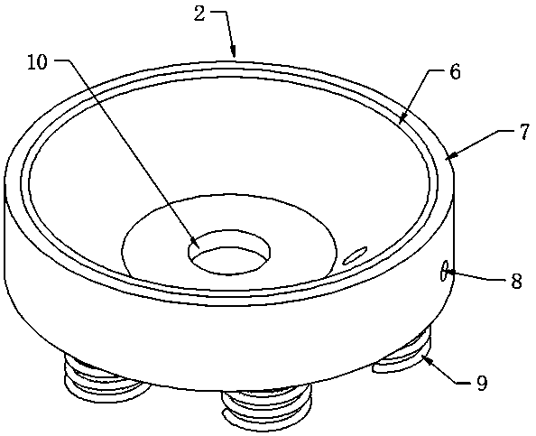
[0031] see figure 2 , an embodiment provided by the present invention: an exhaust main body for surveying and mapping equipment installation, including a first sealing ring 6, a sleeve 7, a spring 9 and a vent 10, and the first sealing ring 6 is fixed by the sleeve 7 Installed, the spring 9 is uniformly and fixedly connected to the lower end of the sleeve 7, and the vent 10 is hollowed out at the lower end of the sleeve 7.

Embodiment 3

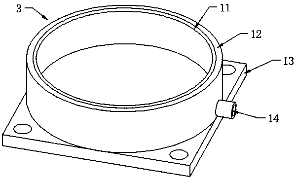
[0033] see image 3 , an embodiment provided by the present invention: a fixing seat for surveying and mapping equipment, including a second sealing ring 11, a sealing shell 12 and a first fixing plate 13, the second sealing ring 11 is fixed by the sealing shell 12 Installation, the second sealing ring 11 is sealed and installed on the outer wall of the sleeve 7, the sleeve 7 is slidably installed on the inner wall of the sealing shell 12, and the first fixing plate 13 is fixed by the lower end of the sealing shell 12 connect.


PUM


Abstract

The invention discloses mapping equipment. An installing butt-joint structure is included and comprises an exhaust body, a fixing base, a butt-joint base and a suction cup body. The lower end of the butt-joint base is adsorbed and fixed to the upper end of the exhaust body. The lower end of the exhaust body is arranged at the upper end of the fixing base in a sliding manner. The exhaust body is adsorbed and fixed through the fixing base. The suction cup body is fixedly installed through the fixing base. The exhaust body comprises a first seal ring, a sleeve disc, springs and a ventilation port. The first seal ring is fixedly installed through the sleeve disc. The springs are evenly and fixedly connected to the lower end of the sleeve disc. The ventilation port is formed in the lower end ofthe sleeve disc in a hollow manner. The fixing base comprises a second seal ring, a seal shell cover and a first fixing plate. The second seal ring is fixedly installed through the seal shell cover.By means of the mapping equipment, installing and butt-joint work of a machine body of a target mapping instrument and a triangular frame of the target mapping instrument can be convenient, and the usage requirement is better met.

Description

technical field [0001] The invention relates to surveying and mapping equipment, an installation method and a key structure for installation thereof, which belong to the field of surveying and mapping equipment and related technologies. Background technique [0002] When a conventional surveying instrument is assembled with its triangle three, it is necessary to align the installation hole of the surveying instrument with the installation point first, and then carry out the assembly work. Since the installation hole and the installation point are difficult to align, resulting in difficult installation, so urgently A solution that alleviates the above-mentioned problems is needed. Contents of the invention [0003] The object of the present invention is to provide a surveying and mapping equipment, an installation method and a key structure for installation thereof, so as to solve the problems raised in the above-mentioned background technology. [0004] In order to achiev...

Claims


Application Information

Patent Timeline
Patent Type & Authority Applications(China)
IPC IPC(8): F16M13/02F16M11/04F16M7/00F16B47/00F16J15/06F16K15/18F16K15/20
CPCF16B47/00F16J15/06F16K15/18F16K15/205F16M7/00F16M11/04F16M13/022
Inventor 潘明哲
Owner XIANGTAN UNIV
Why Eureka
Try Eureka