
Large complex mold element separating and combining method and device

A combination method and unit group technology, applied in the direction of coating, etc., can solve the problems of surface defects, design and processing difficulties, and low molding efficiency of products, so as to facilitate mold clamping, installation and demoulding, and reduce processing difficulty. The effect of convenient installation and combination

Inactive Publication Date: 2014-02-12
BEIJING UNIV OF CHEM TECH +1
View PDF7 Cites 2 Cited by
  • Summary
  • Abstract
  • Description
  • Claims
  • Application Information

AI Technical Summary

Problems solved by technology

[0004] The purpose of the present invention is to design a large and complex mold unit segmentation and combination method and device for the phenomena of difficult mold design and processing, troublesome loading and unloading, low molding efficiency, and prone to surface defects in the process of forming large and complex rotational plastic products. , to provide a mold mechanism and method of use that overcome the above shortcomings, process high-precision rotational plastic molds, facilitate use and maintenance, and improve the precision and production efficiency of rotational plastic products

Method used


Image

  • Large complex mold element separating and combining method and device
  • Large complex mold element separating and combining method and device
  • Large complex mold element separating and combining method and device

Examples


Embodiment 1

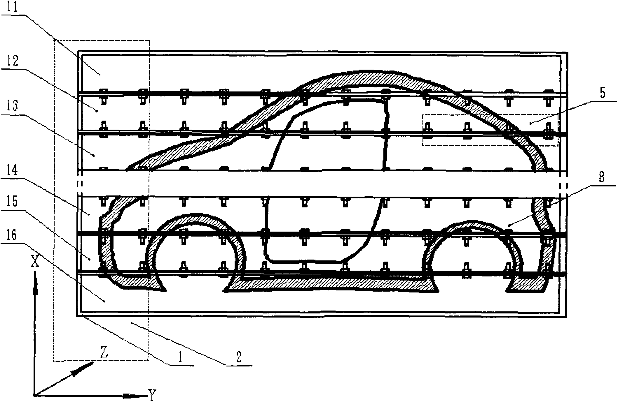
[0028] A large and complex mold unit segmentation and combination method and device of the present invention are segmented effect diagrams along the X direction, such as image 3 with Figure 4 As shown, when the shape and size of the mold to be processed are suitable for unit block along the X direction, 1 can be used # Combination of die unit group 2, 1 # Die unit group 2 mainly includes: X n Die Micron 11, X (n-1) Die Micron 12, X (n-2) Mold microelement 13,...,X 3 Die Micron 14, X 2 Die Micron 15, X 1 There are 16 mold elements, and each mold element in the X direction passes through 1 # The bolt assembly 5 is connected and fixed. If the mold needs to be opened and closed, the matching plane of the two mold elements can be selected according to the shape of the product, the precision of the processed product, and the difficulty of the mold opening and closing station. Actions, e.g. select X (n-2) Mold Micron 13 with X 3 Die micro-unit 14 is used for opening and c...

Embodiment 2

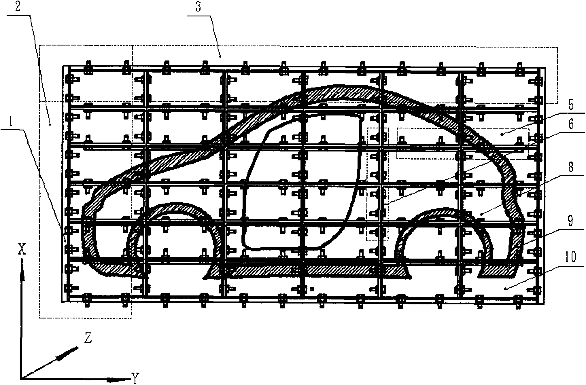
[0030] A large and complex mold unit segmentation and combination method and device of the present invention segmentation effect diagram along the Y direction, as shown Figure 5 As shown, when the shape and size of the mold to be processed are suitable for unit block along the Y direction, 2 can be used # Combination of die unit group 3, 2 # Die unit group 3 mainly includes Y 1 Mold Microelement 17, Y 2 Die micro-element 18,...,Y 3 Mold Microelement 19, Y (n-2) Mold Microelement 20, Y (n-1) Mold Microelement 21, Y n Die micro-units 22, and each mold micro-unit in the Y direction passes through 2 # The bolt assembly 6 is connected and fixed. If it is necessary to open and close the mold, the matching plane of the two mold elements can be selected according to the shape of the product, the precision of the processed product, and the difficulty of the mold opening and closing station. Actions, e.g. select Y 3 Mold Microelement 19 and Y (n-2) Mold micro-element 20 is use...

Embodiment 3

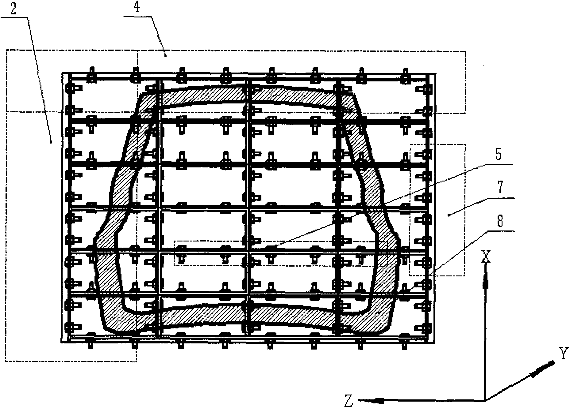
[0032] A large and complex mold unit segmentation and combination method and device of the present invention are segmented effect diagrams along the Z direction, such as Image 6 As shown, when the shape and size of the mold to be processed are suitable for unit block along the Z direction, 3 can be used # Combination of die unit groups 4, 3 # Die unit group 4 mainly includes: Z 1 Mold Microelement 23, Z 2 Mold Microelement 24,...,Z (n-1) Mold Microelement 25, Z n Die micro-units 26, and each mold micro-unit in the Z direction passes through 3 # The bolt assembly 7 is connected and fixed. If it is necessary to open and close the mold, the matching plane of the two micro-elements of the mold can be selected according to the shape of the product, the precision of the processed product, and the difficulty of the mold opening and closing station. Operation, for example: select Z 2 Mold Micron 24 with Z (n-1) Mold element 25 carries out opening and closing mould.

[0033] F...


PUM


Abstract

The invention relates to a large complex mold element separating and combining method and a large complex mold element separating and combining device. The large complex mold element separating and combining method comprises the following steps: separating a large complex or heavy mold device into a plurality of arrays; determining according to shapes and sizes of products required to be processed in selecting an element separating and combining method, and separating a large and heavy solid mold into mold elements at the X direction, or the Y direction or the Z direction; separating elements at two directions or three directions according to partial shapes of products; labeling each mold unit according to coordinates; then processing and manufacturing the mold micro elements; and assembling the mold micro elements according to labels so as to form a complete set of mold. The device adopting the method mainly comprises a mold frame, a No.1 mold unit group, a No.2 mold unit group, a No.3 mold unit group, a No.1 bolt component, a No.2 bolt component and a No.3 bolt component. Large and heavy screw plastic molds can be broken into parts through the element separating structure and combining method, thereby reducing the integral processing difficulty of large complex molds, and facilitating maintenance.

Description

technical field [0001] The invention relates to a structure and a molding method of a mold, in particular to a method and a device for combining large and complex hollow plastic product rotation molding molds. technical background [0002] At present, rotational molding products have gradually changed from single containers to high-precision vehicles, ships and other products to meet the needs of advanced manufacturing industries. Therefore, rotational molding has higher requirements on the machining accuracy of the rotational mold, the speed of opening and closing the mold, and the disassembly efficiency of the product. The production methods of rotational plastic mold mainly adopt three types: aluminum alloy casting mold, aluminum alloy welding mold and steel plate welding mold. The assembly method of the mold is basically connected and fixed by a large number of bolts. When processing rotationally molded products of different sizes and shapes, especially those with compl...

Claims


Application Information

Patent Timeline
Patent Type & Authority Applications(China)
IPC IPC(8): B29C41/38
Inventor 杨卫民秦柳肖勇丁玉梅虞华春朱国才
Owner BEIJING UNIV OF CHEM TECH
Learn More