Electric power fitting wear testing machine

A technology of wear test and electric fittings, which is applied in the direction of mechanical equipment, testing wear resistance, engine components, etc., can solve the problems of easily blocked connecting rods sliding up and down, damage of internal parts of the machine, movement of electric fittings, etc., to ensure normal sliding up and down , rapid lubrication, and guarantee the effect of placement

Inactive Publication Date: 2020-08-28
吴章忠
View PDF0 Cites 2 Cited by
  • Summary
  • Abstract
  • Description
  • Claims
  • Application Information

AI Technical Summary

Problems solved by technology

[0003] However, there are still some drawbacks in the existing electric fittings wear tester. After the machine has been in operation for a long time, dust will fall on the sliding gap between the telescopic cylinder and the connecting rod, which will easily block the sliding of the connecting rod in the telescopic cylinder. In addition, when the machine The vibration generated during operation may easily cause the electric fittings to move during the test on the test bench, and the vibration generated when the machine cannot buffer the operation may easily cause damage to the internal parts of the machine. For this reason, we propose a Electric fittings wear tester

Method used


Image

  • Electric power fitting wear testing machine
  • Electric power fitting wear testing machine
  • Electric power fitting wear testing machine

Examples


Embodiment Construction

[0026] The following will clearly and completely describe the technical solutions in the embodiments of the present invention with reference to the accompanying drawings in the embodiments of the present invention. Obviously, the described embodiments are only some, not all, embodiments of the present invention. Based on the embodiments of the present invention, all other embodiments obtained by persons of ordinary skill in the art without making creative efforts belong to the protection scope of the present invention.

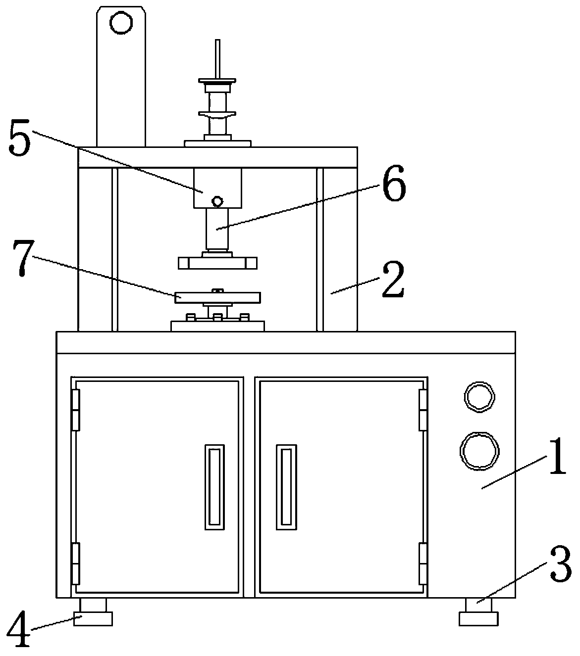
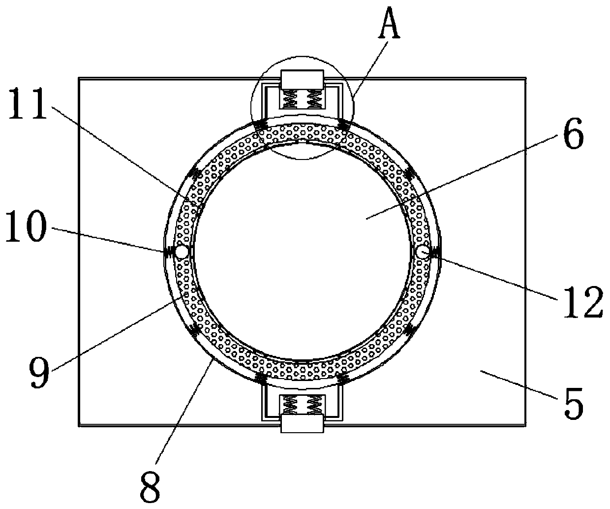
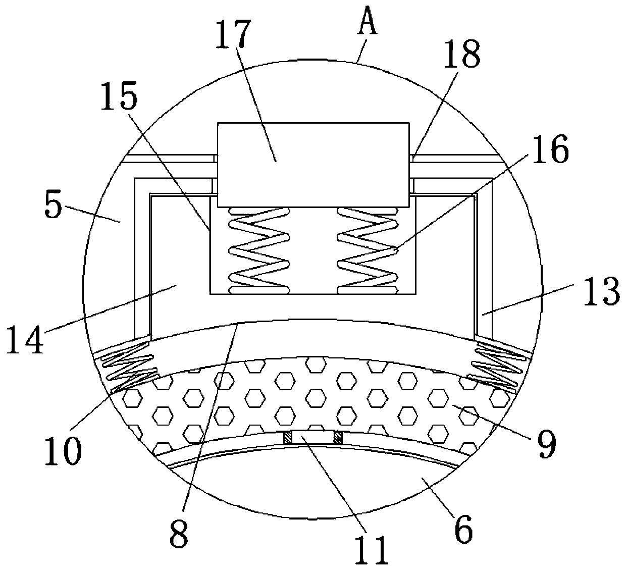
[0027] see Figure 1-5 , the present invention provides a technical solution: a wear tester for electrical fittings, comprising a machine body 1, a lubricating mechanism, a fixing mechanism, and a shock absorbing mechanism, the top surface of the machine body 1 is provided with a frame 2, and the frame 2 The front surface is provided with a telescopic tube 5, and the front surface of the frame 2 is provided with a connecting rod 6 at the bottom end of the tele...


PUM


Abstract

The invention discloses an electric power fitting wear testing machine. The machine comprises a machine body, a lubricating mechanism, a fixing mechanism and a damping mechanism, and a rack is arranged on the surface of the top end of the machine body. A telescopic cylinder is arranged on the front surface of the rack, a connecting rod is arranged at the position, located at the bottom end of thetelescopic cylinder, of the front surface of the rack, the connecting rod penetrates through the surface of the bottom end of the telescopic cylinder, one side of the connecting rod is located in thetelescopic cylinder, and the lubricating mechanism is located at the joint of the telescopic cylinder and the connecting rod and comprises a lubricating sleeve. By arranging the lubricating sleeve, the service life of the connecting rod is prolonged, it is guaranteed that the connecting rod can normally slide up and down, and meanwhile the working efficiency of the machine is improved; through thearrangement of a placement groove, the placement effect of the test bed on the electric power fittings is guaranteed, and the abrasion quality of the machine on the test electric power fittings is improved; and through the arrangement of the damping plate, the stability of the machine is improved, and the service life of the machine is prolonged.

Description

technical field [0001] The invention belongs to the technical field of wear testing machines, and in particular relates to a wear testing machine for electric fittings. Background technique [0002] Power fittings such as U-shaped rings and suspension clamps commonly used in the construction of transmission lines need to bear large vertical loads and large swings during their use. In such cases, many power fittings use Less than a year later, serious wear and tear occurred, thereby posing potential safety hazards and requiring regular replacement. While consuming manpower, financial and material resources, it also affected normal production and life. Therefore, users must clearly grasp the wear resistance of the above-mentioned power fittings before use, and conduct wear tests on power fittings from different companies and even different batches of power fittings, so as to select power fittings with better wear resistance. [0003] However, there are still some drawbacks in...

Claims


Application Information

Patent Timeline
Patent Type & Authority Applications(China)
IPC IPC(8): G01N3/56G01N3/02F16N7/14F16F15/08
CPCF16F15/085F16N7/14G01N3/02G01N3/56
Inventor 吴章忠
Owner 吴章忠
Why Eureka
Try Eureka