Assembled optical cable cross-connecting box capable of expanding capacity

A technology of optical cable transfer box and transfer box, which is applied in the field of transfer box to achieve the effect of improving stability

Inactive Publication Date: 2020-08-28
班俊超
View PDF1 Cites 0 Cited by
  • Summary
  • Abstract
  • Description
  • Claims
  • Application Information

AI Technical Summary

Problems solved by technology

[0005] (1) How to solve the problem of the modularized fixed installation of the transfer box. In one aspect disclosed by the embodiment of the present invention, the base of the transfer box, the first combination cabinet and the second combination cabinet are mortised and fixed to facilitate the transfer box Carry out modular assembly, the base of the transfer box is fixed and installed in the working area through the isolation base, align the upper end of the first combination cabinet with the base of the transfer box, and slowly move the first mortise plate at the lower end of the first combination cabinet to the base of the transfer box The interior is close to the surrounding position until it is tenoned and fixed with the second mortise plate inside the transfer box base to realize the combination between the transfer box base and the first combination cabinet, and the disassembly and assembly are simple and efficient. The first combination cabinet and the second combination cabinet The second combination cabinet is fixed by mortise joint, and the top plate is connected and fixed with the second combination cabinet, so as to realize the modular installation of the main body of the transfer box, which can effectively improve the efficiency of disassembly and assembly of the transfer box, and overcome the problem that the transfer box cannot be modularized and disassembled in the existing scheme. combined defects;

Method used


Image

  • Assembled optical cable cross-connecting box capable of expanding capacity
  • Assembled optical cable cross-connecting box capable of expanding capacity
  • Assembled optical cable cross-connecting box capable of expanding capacity

Examples


Embodiment Construction

[0034] The technical solutions of the present invention will be clearly and completely described below in conjunction with the embodiments. Apparently, the described embodiments are only some of the embodiments of the present invention, not all of them. Based on the embodiments of the present invention, all other embodiments obtained by persons of ordinary skill in the art without creative efforts fall within the protection scope of the present invention.

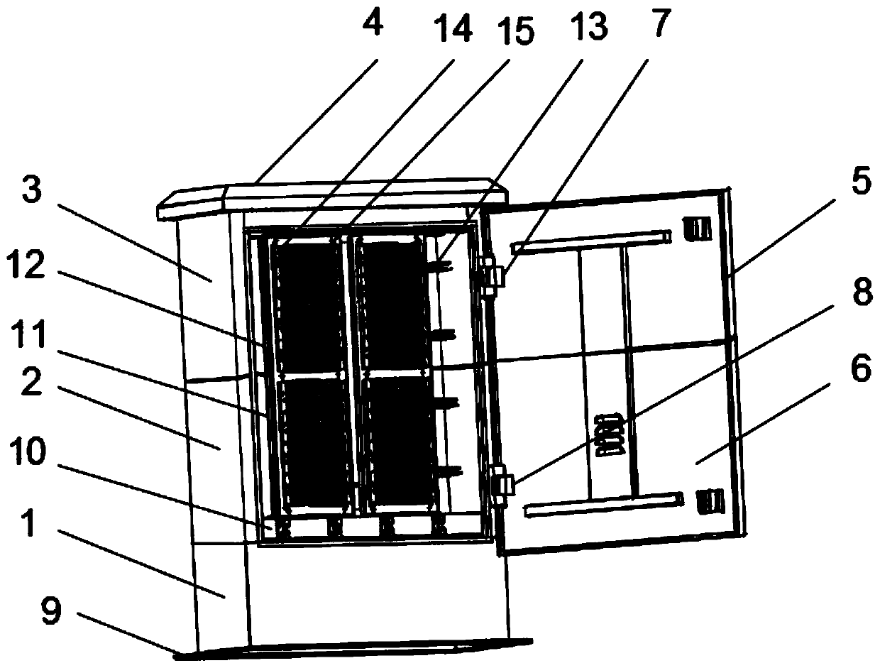
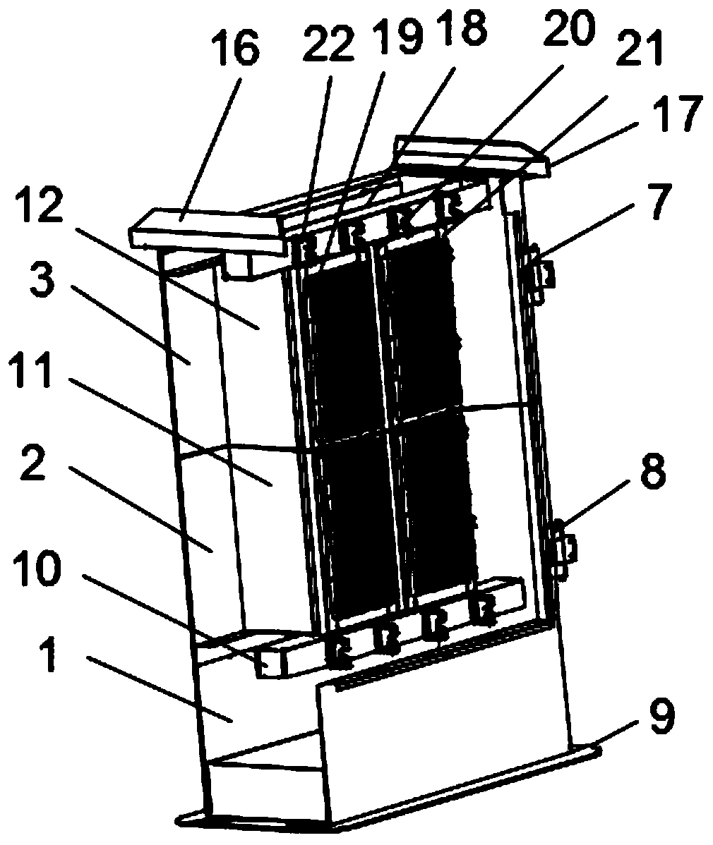
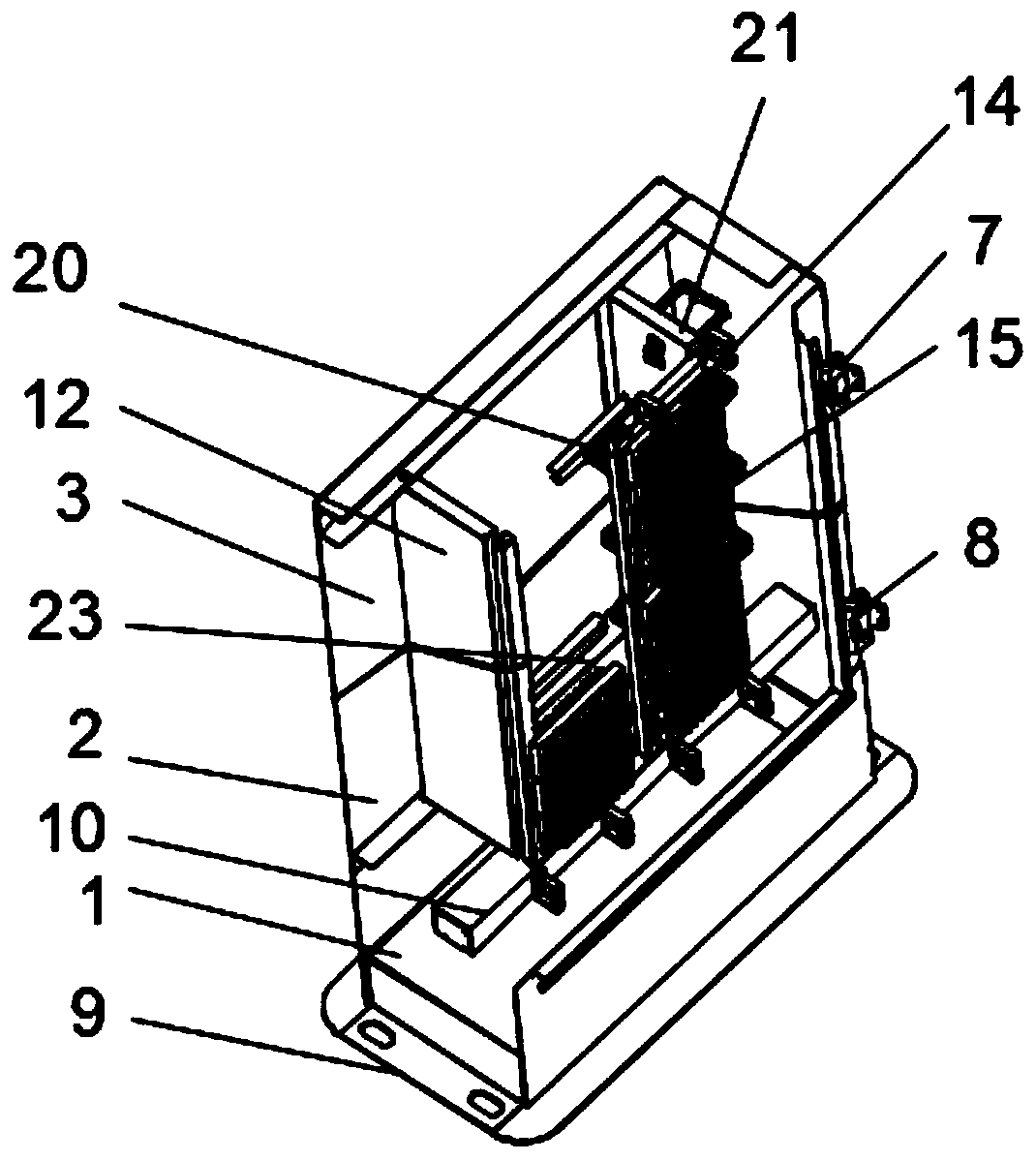
[0035] Such as Figure 1-6 As shown, an expandable and expandable assembled optical cable transfer box includes a transfer box base 1, a first combination cabinet 2 and a second combination cabinet 3, and the transfer box base 1 is located between the first combination cabinet 2 and the second combination cabinet 3, the second combination cabinet 3 is located at the top of the transfer box base 1 and the first combination cabinet 2, and the first combination cabinet 2 is located between the transfer box base 1 and the secon...


PUM


Abstract

The invention discloses an assembled optical cable cross-connecting box capable of expanding capacity. Through the arrangement that the cross-connecting box base, the first combined cabinet and the second combined cabinet are joggled and fixed, modular assembly of the cross-connecting box is facilitated; the top plate and the second combined cabinet are connected and fixed, modular installation ofthe cross-connecting box body is achieved, the disassembly and assembly efficiency of the cross-connecting box can be effectively improved, and the defect that in an existing scheme, the cross-connecting box cannot be disassembled, assembled and combined in a modular mode is overcome; by arranging the first combined cabinet and the second combined cabinet, if the capacity of the cross-connectingbox needs to be expanded, a plurality of combined cabinets continue to be joggled and fixed to the upper end of the second combined cabinet in the mode that the second combined cabinet and the first combined cabinet are joggled and fixed, and the purpose of expanding the space of an existing cross-connecting box can be achieved; and through cooperative use of the arranged clamping strips, spring buckles, telescopic springs and limiting columns, the limiting columns are used for limiting stretching and retracting of the spring buckles, and the stability between the cross-connecting box modulesis further improved on the basis of joggling and fixing.

Description

technical field [0001] The invention relates to the technical field of transfer boxes, in particular to an expandable and expandable assembled optical cable transfer box. Background technique [0002] The optical cable transfer box is a transfer device that provides cable termination and jumper connection for the backbone layer optical cable and the wiring layer optical cable. It is connected with the optical cable of the distribution layer. The optical cable transfer box is a connecting device installed outdoors. The most fundamental requirement for it is to be able to withstand drastic changes in the climate and harsh working environment, and to be waterproof, waterproof, dustproof, and insect-proof. It has the characteristics of strong resistance to rodent damage and impact damage, and must be able to withstand relatively harsh external environments. Therefore, the outside of the box has relatively high requirements for waterproof, moisture-proof, dust-proof, impact damag...

Claims


Application Information

Patent Timeline
Patent Type & Authority Applications(China)
IPC IPC(8): G02B6/44
CPCG02B6/4446
Inventor 班俊超
Owner 班俊超
Why Eureka
Try Eureka