Eureka AIR delivers breakthrough ideas for toughest innovation challenges, trusted by R&D personnel around the world.

Ripple elimination device of power supply of communication system

A technology of power supply and communication system, which is applied in the direction of battery circuit devices, circuit devices, load supply circuits, etc. It can solve problems affecting the throughput of transmitted data, eliminate dynamic ripple, and affect the quality of radio frequency signals, so as to improve the quality of radio frequency signals and data throughput, the effect of eliminating dynamic ripple

Active Publication Date: 2020-08-28
上海联虹技术有限公司
View PDF5 Cites 1 Cited by
  • Summary
  • Abstract
  • Description
  • Claims
  • Application Information

AI Technical Summary

Problems solved by technology

[0002] Communication systems generally use switching power supplies for power supply. When the communication system sends radio frequency signals, the load of the switching power supply is large. When the communication system receives radio frequency signals, the load of the switching power supply is small. In the actual communication process, due to the radio frequency of the communication system Signal transmission and reception are carried out alternately, resulting in the load of the switching power supply in a state of constant size change. In the process of dynamically adjusting the load, the following two problems are prone to occur: (1) The dynamic ripple is large, which affects the quality of the RF signal; (2) The dynamic response is not timely, which affects the throughput of transmitted data
[0004] However, the technical solutions provided by the prior art can only optimize and alleviate the dynamic ripple of the switching power supply to a certain extent, and do not really eliminate the dynamic ripple

Method used


Image

  • Ripple elimination device of power supply of communication system

Examples


Embodiment Construction

[0021] The following will clearly and completely describe the technical solutions in the embodiments of the present invention with reference to the accompanying drawings in the embodiments of the present invention. Obviously, the described embodiments are only some, not all, embodiments of the present invention. Based on the embodiments of the present invention, all other embodiments obtained by persons of ordinary skill in the art without creative efforts fall within the protection scope of the present invention.

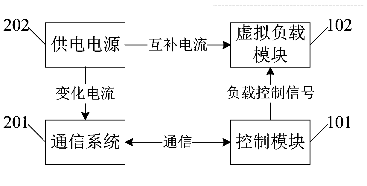
[0022] An embodiment of the present invention provides a ripple elimination device for a power supply of a communication system, see figure 1 As shown, it is a schematic structural diagram of a preferred embodiment of a ripple elimination device for a power supply of a communication system provided by the present invention, and the device includes a control module 101 and a dummy load module 102;

[0023] The control module 101 is used to obtain and record the curr...


PUM


Abstract

The invention discloses a ripple elimination device for a power supply of a communication system. The ripple elimination device comprises a control module and a virtual load module, wherein the control module is used for obtaining and recording the current communication power of a communication system, obtaining a current virtual load corresponding to the current communication power according to apreset power-load comparison table, generating a corresponding load control signal according to the current virtual load, and sending the load control signal to the virtual load module, and the virtual load module is used for adjusting the size of a virtual load according to the received load control signal so as to carry out load compensation on the power supply of the communication system according to the adjusted virtual load. By adopting the technical scheme of the invention, dynamic ripples of the power supply of the communication system can be eliminated, and the radio frequency signalquality and the data throughput are improved.

Description

technical field [0001] The invention relates to the technical field of wireless communication, in particular to a ripple elimination device for a power supply of a communication system. Background technique [0002] Communication systems generally use switching power supplies for power supply. When the communication system sends radio frequency signals, the load of the switching power supply is large. When the communication system receives radio frequency signals, the load of the switching power supply is small. In the actual communication process, due to the radio frequency of the communication system Signal transmission and reception are carried out alternately, resulting in the load of the switching power supply in a state of constant size change. In the process of dynamically adjusting the load, the following two problems are prone to occur: (1) The dynamic ripple is large, which affects the quality of the RF signal; (2) The dynamic response is not timely, which affects ...

Claims


Application Information

Patent Timeline
IPC IPC(8): H02J7/00
CPCH02J7/0063
Inventor 康冬亮
Owner 上海联虹技术有限公司
Why Eureka
Eureka Blog
Learn More