
Filter

A filter and parallel resonator technology, applied in the field of filtering, can solve the problems of deterioration of insertion loss, narrowing of bandwidth, deterioration of other frequency suppression, etc., to achieve the effect of suppressing the passage of signals

Pending Publication Date: 2020-08-28
TIANJIN UNIV +1
View PDF3 Cites 0 Cited by
  • Summary
  • Abstract
  • Description
  • Claims
  • Application Information

AI Technical Summary

Problems solved by technology

[0003] At present, in the existing technology, the improvement of out-of-band suppression is generally achieved by increasing the number of stages or by moving the position of the out-of-band transmission zero point, but this method will bring about problems such as insertion loss deterioration and other frequency suppression deterioration; for roll-off The improvement is generally achieved by using a smaller electromechanical coupling coefficient and an additional resonator, but this method will reduce the bandwidth and increase the area of ​​the resonator, which will lead to the deterioration of the insertion loss and the increase of the chip size.

Method used


Image

  • Filter
  • Filter
  • Filter

Examples


Embodiment Construction

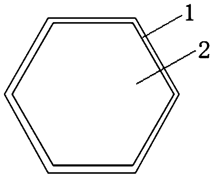
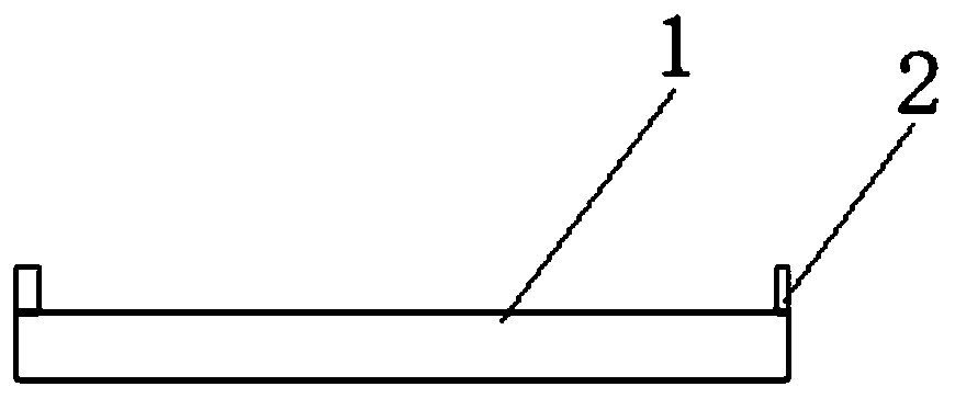
[0031] This embodiment provides a filter, including a series-parallel resonator 4 circuit, the series-parallel resonator 4 circuit includes a plurality of series resonators 3 and a plurality of parallel resonators 4, at least one series resonator 3 and / or at least one The surface of the upper electrode 1 of the parallel resonator 4 is provided with an annular protrusion 2; the annular protrusion 2 has a limited width, and the depth of the filter transmission zero point is adjusted according to the size of the limited width; the annular protrusion 2 has a limited height, and according to the size of the limited height Adjusts the position of the filter transmission zero.

[0032] like figure 1 and figure 2 As shown, the annular protrusion 2 is disposed on the surface of the upper electrode 1 of the resonator, preferably, the protrusion structure is disposed at the edge of the surface of the upper electrode 1 . After replacing one or part of the resonators in the filter with ...


PUM

PropertyMeasurementUnit
Widthaaaaaaaaaa

Abstract

The invention relates to the technical field of filtering, in particular to a filter, which comprises a series-parallel resonator circuit. The series-parallel resonator circuit comprises a plurality of series resonators and a plurality of parallel resonators, and an annular bulge is arranged on the surface of an upper electrode of at least one series resonator and / or at least one parallel resonator. The annular bulge has a limited width, and the depth of a transmission zero point of the filter is adjusted according to the limited width. The annular projection has a limited height, and the position of the transmission zero point of the filter is adjusted according to the limited height. According to the technical scheme, by changing the structure of the filter and increasing additional resonance generated by the annular protrusions, an additional transmission zero point is formed outside a band, and compared with the prior art, the filter does not need to increase the filter stage number or move the zero point of the specific frequency outside the band, and deterioration of other performance cannot be caused.

Description

technical field [0001] The present invention relates to the technical field of filtering, in particular to a filter. Background technique [0002] The performance of filters, duplexers and multiplexers in the front end of radio frequency communication has higher and higher requirements. With the increase of frequency bands, the demand for out-of-band suppression is becoming more and more stringent; at the same time, adjacent-band suppression has always been a One of the most important indicators of the filter, so the requirements for roll-off are getting higher and higher. It can be seen that in the design of the filter, the improvement of out-of-band rejection (for the far band) and roll-off (for the adjacent band) is one of the ultimate goals. [0003] At present, in the existing technology, the improvement of out-of-band suppression is generally achieved by increasing the number of stages or by moving the position of the out-of-band transmission zero point, but this meth...

Claims


Application Information

Patent Timeline
IPC IPC(8): H03H9/46
CPCH03H9/46
Inventor 庞慰蔡华林
Owner TIANJIN UNIV
Learn More