Hotbed chives spray-washing equipment
An equipment and technology for chives, applied in the field of chives spraying equipment, can solve problems such as cumbersome movements, and achieve the effects of saving water resources and being easy to place.
- Summary
- Abstract
- Description
- Claims
- Application Information
AI Technical Summary
Problems solved by technology
Method used
Image
Examples
Embodiment 1
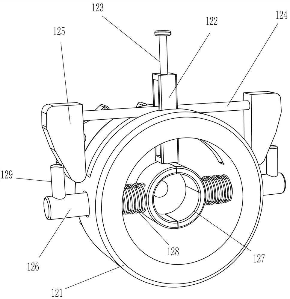
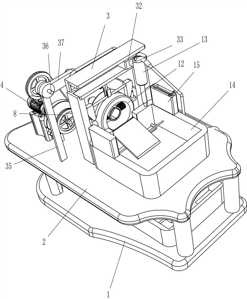
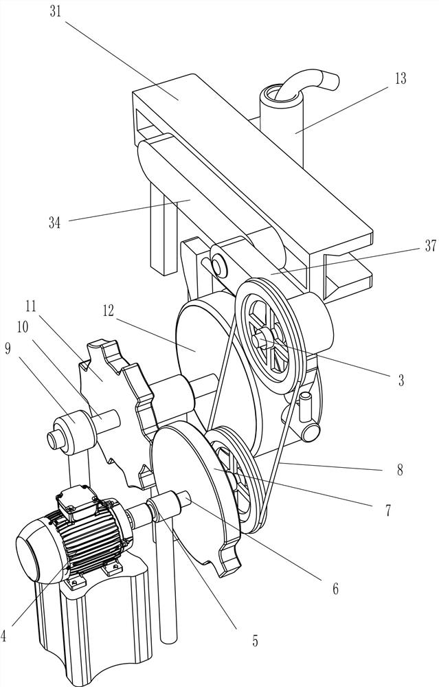
[0040] A kind of leek spray washing equipment, such as Figure 1-2 As shown, it includes a spray washing seat 1, a mounting plate 2, a spray washing mechanism 3, a driving motor 4, a vertical frame 5, a driving shaft 6, a driving missing gear 7, a belt transmission mechanism 8, a fixed frame 9, a lower transmission shaft 10, Transmission gear 11, clamping mechanism 12, water spray gun 13 and water collection frame 14, installation plate 2 is provided on the top of spray seat 1, spray washing mechanism 3 is provided on the rear side of the top of the installation seat, and a drive is provided on the rear side of the top of the installation seat. Motor 4 and vertical frame 5, drive motor 4 and vertical frame 5 are positioned at the rear side of spray washing mechanism 3, vertical frame 5 is positioned at drive motor 4 fronts, and the output shaft of drive motor 4 front ends is connected with driving rotating shaft 6, and driving rotating shaft 6 and vertical Frame 5 is rotationa...
Embodiment 2
[0043] On the basis of Example 1, such as Figure 1-3As shown, the spray washing mechanism 3 includes a slide rail 31, a slide block 32, a connecting rod 33, a swing plate 34, a support plate 35, an upper transmission shaft 36 and a rotating plate 37, and the top of the mounting plate 2 is connected with a slide rail 31 in the middle. Rail 31 is positioned at the rear top of water collecting frame 14, slide rail 31 is provided with slide block 32, and the front side of slide block 32 is provided with connecting rod 33, and the front end of connecting rod 33 is connected with water spray gun 13, and the rear side of slide block 32 swings A swing plate 34 is connected in the form of a swing plate, and a support plate 35 is provided at the left side of the top of the mounting plate 2. The support plate 35 is located between the vertical frame 5 and the slide rail 31. The top of the support plate 35 is connected with an upper transmission shaft 36 in a rotational manner. The rear ...
Embodiment 3
[0048] On the basis of Example 2, such as figure 1 and Figure 4-5 Shown, also comprise installation box 15, round rod 17, pull bar 18, arc bar 19, swing plate 20, wire conduit 21 and backguy 22, the top wall right side rear of water collecting frame 14 is provided with installation box 15, The top of the installation box 15 is provided with a chute 16, and the sliding type in the chute 16 is provided with a circular rod 17, and the top of the circular rod 17 is provided with a pull bar 18, and the left and right sides of the top of the installation box 15 are provided with arc rods 19. , the rear side of the water collecting frame 14 is rotatably connected with a swing plate 20, the inner rear right of the water collecting frame 14 is provided with a conduit 21, the conduit 21 is provided with a stay wire 22, and the left end of the pull wire 22 is connected behind the bottom of the swing disk 20 Side, the right end of stay wire 22 connects circular bar 17 bottoms.
[0049]...
PUM
 Abstract
Description
Claims
Application Information
 - R&D
- Intellectual Property
- Life Sciences
- Materials
- Tech Scout
- Unparalleled Data Quality
- Higher Quality Content
- 60% Fewer Hallucinations
Browse by: Latest US Patents, China's latest patents, Technical Efficacy Thesaurus, Application Domain, Technology Topic, Popular Technical Reports.
© 2025 PatSnap. All rights reserved.Legal|Privacy policy|Modern Slavery Act Transparency Statement|Sitemap|About US| Contact US: help@patsnap.com


