Sand box structure for lost foam casting

A technology of lost foam casting and sand box, which is applied to casting molding equipment, casting molds, mold boxes, etc. It can solve the problems of low casting efficiency and cannot be improved, and achieve the effect of improving casting efficiency

Active Publication Date: 2020-09-01
山西博鹰铸造股份有限公司
View PDF4 Cites 0 Cited by
  • Summary
  • Abstract
  • Description
  • Claims
  • Application Information

AI Technical Summary

Problems solved by technology

[0004] The invention provides a sand box structure for lost foam casting, which has the advantages that the dry sand in contact with the outer surface of the model is compacted first, and then the amplitude can be increased to increase the casting efficiency, and it solves the problem that the amplitude is limited to a certain range and cannot be increased. low efficiency

Method used


Image

  • Sand box structure for lost foam casting
  • Sand box structure for lost foam casting
  • Sand box structure for lost foam casting

Examples


Embodiment 1

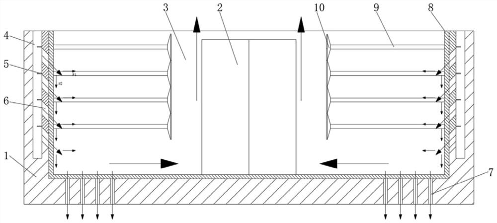
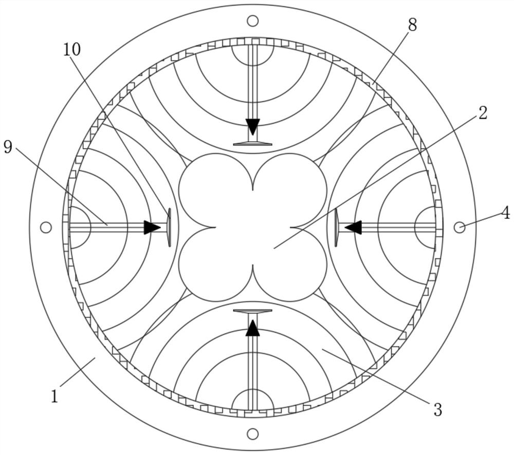
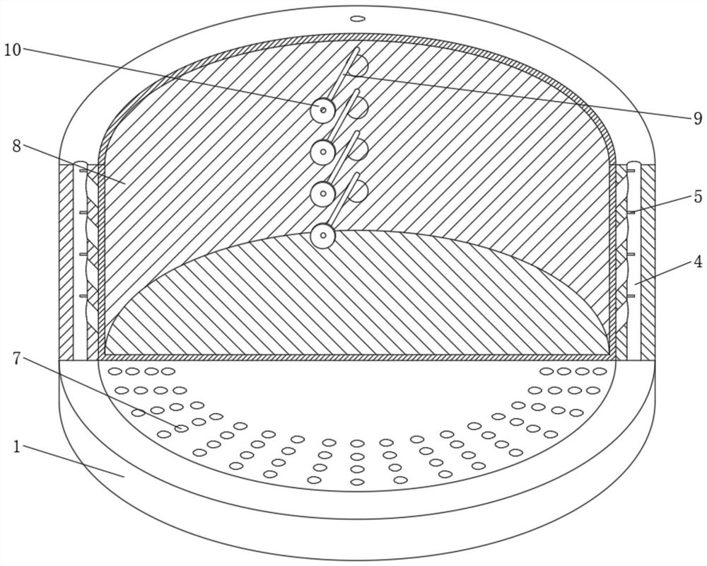
[0027] Fix the model 2 into the inner cavity of the sand box 1, fill the sand box 1 with dry sand 3, provide a certain amplitude to the sand box 1, so that the sand box 1 drives the dry sand 3 to shake, and at the same time pass into the air hole 4 The high-speed airflow, the airflow hits the vertically distributed vibrating diaphragm 5, the vibrating diaphragm 5 vibrates and produces sound waves, and part of the sound waves are directly transmitted to the dry sand 3, so that the dry sand 3 has a moving force towards the center, making the dry sand 3. The surface of the model 2 is first compacted, and a part of the sound wave is directly transmitted to the vicinity of the model 2 through the sound transmission rod 9 and the sound reinforcement plate 10 to act on the dry sand 3, so that the dry sand 3 near the model 2 is under the action of the sound wave The compacting effect is better. At the same time, the high-speed airflow circulating in the airflow hole 4 passes through th...

Embodiment 2

[0029] When the model 2 is of a regular shape, the compaction of the dry sand 3 can be achieved by placing a compaction plate 11 above the dry sand 3 near the outer surface of the model 2. The dry sand 3 has a pre-compression effect, and the compressed dry sand 3 shakes smaller under the vibration of the sand box 1, so that the vibration amplitude of the sand box 1 can be increased, and the compaction plate 11 After the dry sand 3 below is further compacted, the vibration amplitude of the sand box 1 can be increased again, so that the vibration and compaction efficiency of the remaining dry sand 3 is higher.


PUM


Abstract

The invention relates to the technical field of casting equipment, and discloses a sand box structure for lost foam casting. The sand box structure comprises a sand box, a model is fixedly arranged inthe middle of an inner cavity of the sand box, the inner cavity of the sand box is filled with dry sand, and airflow holes are formed in the inner wall of the sand box; a vibration diaphragm is fixedly arranged at one side, close to the inner cavity of the sand box, of the interior of each airflow hole, and an inclined hole is formed in each airflow hole and located below the vibrating diaphragm.Through the sand box structure for the lost foam casting, the vibrating diaphragms vibrate to generate sound waves through flowing airflow, the sound waves are transmitted to the dry sand to achievea compaction effect towards the center on the dry sand, so that the dry sand is compacted on the outer surface of the model by a certain thickness at first, then the certain amplitude of the sand boxis increased, and the compaction efficiency of the remaining dry sand is improved; the problems that existing dry sand is compacted upwards layer by layer at the bottom of the inner cavity of the sandbox, the amplitude must be stable, and the compaction efficiency is low are solved, and the casting efficiency of equipment is improved.

Description

technical field [0001] The invention relates to the technical field of casting equipment, in particular to a sand box structure for lost foam casting. Background technique [0002] The sand box for lost foam casting is a special sand box. The basic structure is a box-shaped body with an open top. There are two types of round and square. There are also a few follow-up sand boxes. Put the model into the sand box and fill it with dry sand , under the action of the vibrating mechanism, the dry sand in the sand box vibrates tightly, making the dry sand compact in sequence from the bottom to the top inside the sand box, so that the dry sand is in close contact with the outer surface of the model, and then the metal solution is poured . [0003] In such a sand box structure, during use, since the dry sand is vibrated and compacted sequentially from the bottom to the top, in order to prevent the model from being damaged by the vibrating dry sand, it is necessary to limit the vibrat...

Claims


Application Information

Patent Timeline
Patent Type & Authority Applications(China)
IPC IPC(8): B22C21/14B22C9/04B22C15/14
CPCB22C9/04B22C15/14B22C21/14
Inventor 黄剑
Owner 山西博鹰铸造股份有限公司
Why Eureka
Try Eureka