
Light irradiation device

A light irradiation device and a technology for irradiating light, which are applied in the direction of lighting devices, fixed lighting devices, lighting device components, etc., can solve the problems of heat generation of the frame body and inability to touch the frame body, and achieve the effect of preventing heat generation

Active Publication Date: 2020-09-01
HOYA CORP
View PDF8 Cites 1 Cited by
  • Summary
  • Abstract
  • Description
  • Claims
  • Application Information

AI Technical Summary

Benefits of technology

The technical effect of this patented technology allows for reliable prevention of UV radiation leakage into an illumination system while keeping its temperature low by avoiding excessive heat generation caused by sunlight or other sources on the inside surface of the housing.

Problems solved by technology

This patented technical problem addressed in this patents relating to an improved method for creating high quality printed images without consuming too much energy or requiring longer maintenance compared to traditional methods like laser printers.

Method used


Image

  • Light irradiation device
  • Light irradiation device
  • Light irradiation device

Examples


Embodiment Construction

[0068] Hereinafter, embodiments of the present invention will be described in detail with reference to the drawings. In addition, the same code|symbol is attached|subjected to the same or corresponding part in a drawing, and the description is not repeated.

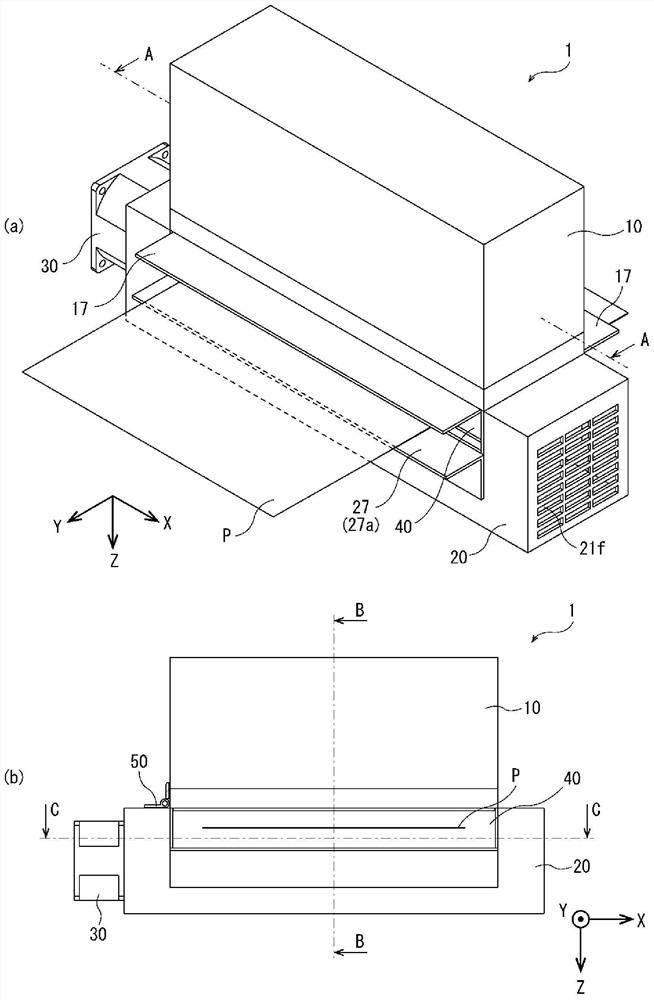
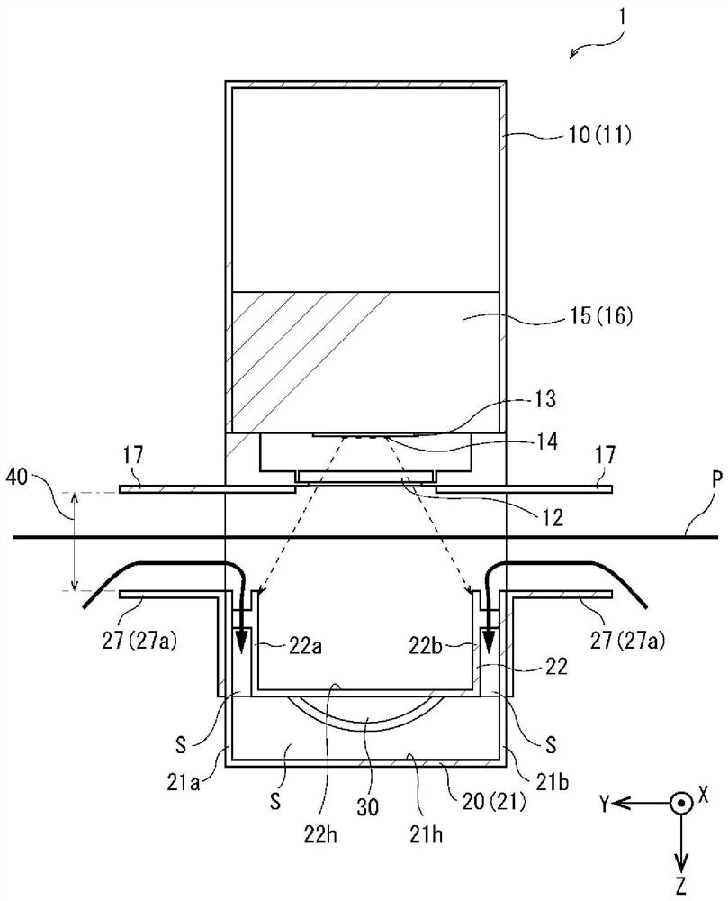
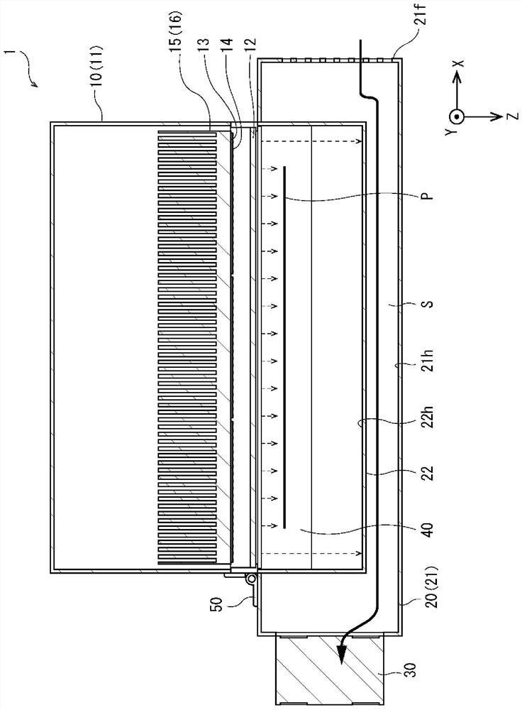
[0069] figure 1 It is a figure which shows the structure of the light irradiation apparatus 1 concerning embodiment of this invention, figure 1 (a) is a perspective view, figure 1 (b) is a front view. in addition, figure 2 is along figure 1 (b) The sectional view of line B-B, image 3 is along figure 1 (a) Cross-sectional view of line A-A. Such as Figure 1 to Figure 3 As shown, the light irradiation device 1 is a device for curing ultraviolet curable resin coated on the surface of a transported object P to be irradiated (such as a recording medium, etc.), and consists of a light source unit 10 arranged above the object P to be irradiated, and The light shielding unit 20 arranged opposite to the light source uni...


PUM


Abstract

The invention provides a light irradiation device that can reliably prevent ultraviolet rays from leaking to the outside of the light irradiation device and can also prevent heat generation of the housing. The light irradiation device of the present invention is a light irradiation device that irradiates light with respect to an irradiation target conveyed along a first direction, and includes a light source unit having a plurality of LED elements that are aligned with the first direction. The second direction of the intersection irradiates light to the illuminated object; and a shading unit,which is arranged opposite to the light source unit across the conveying path of the illuminated object, and shields light so that the light irradiated from the light source unit does not leak to theoutside, the shading unit It has: a light absorption member that absorbs light irradiated from the light source unit; a frame body that houses and supports at least a part of the light absorption member; and a wind tunnel that is formed between the frame body and the light absorption member and makes cooling wind flow through.

Description


Claims


Application Information

Patent Timeline
Owner HOYA CORP
Learn More