Tree transplanting sling

A tree transplanting and spreader technology, applied in the direction of load hanging components, transportation and packaging, etc., can solve the problem of low work efficiency of transplanting trees, and achieve the effects of reducing wrapping, improving stability, and quick separation

Active Publication Date: 2020-09-01
北京胖龙丽景科技有限公司
View PDF9 Cites 0 Cited by
  • Summary
  • Abstract
  • Description
  • Claims
  • Application Information

AI Technical Summary

Problems solved by technology

[0005] The above-mentioned prior art scheme has the following defects: when the transplanted tree is hoisted and transported, it is necessary to wrap the transplanted tree soil ball layer by layer to protect the soil ball. low work efficiency

Method used


Image

  • Tree transplanting sling
  • Tree transplanting sling
  • Tree transplanting sling

Examples


Embodiment 1

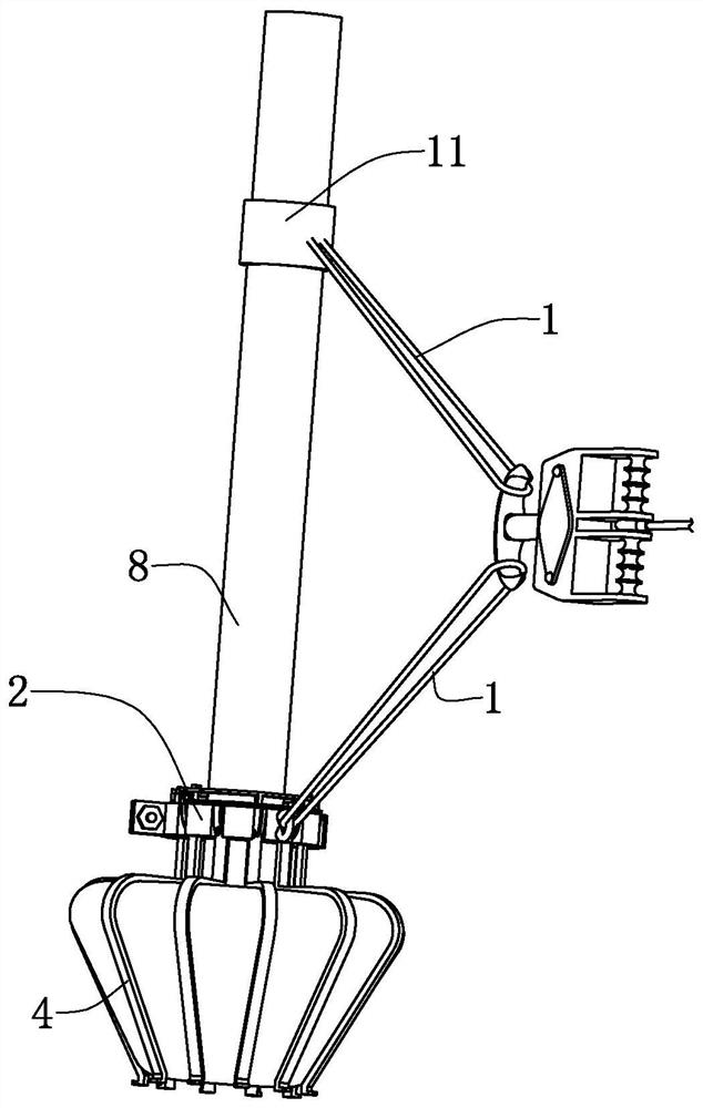
[0048] refer to figure 1 , discloses a tree transplanting sling for the present invention, comprising a sling 1, the sling 1 is a steel wire rope, the sling 1 is used to connect with a hook, one end of the sling 1 is connected with a winding rope 11, and the winding rope 11 is wound and connected On the outside of the trunk of the transplanted tree 8, the winding rope 11 is connected between the center of gravity of the transplanted tree 8 and the soil ball of the transplanted tree 8, and the other end of the suspension rope 1 is detachably connected with a lifting frame, and the lifting frame is used to connect with the soil ball of the transplanted tree 8 .

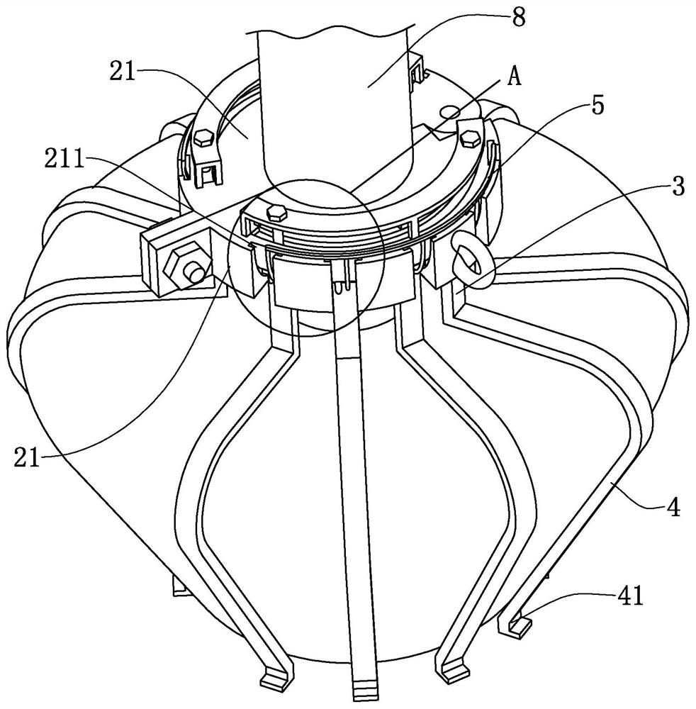
[0049] refer to figure 2 and image 3 , the lifting frame includes a lifting ring 2, and the lifting ring 2 includes a detachably connected arc-shaped suspender 21, and the end of the arc-shaped suspender 21 is sequentially connected to form the suspension ring 2. In this embodiment, there are two arc-shaped suspende...

Embodiment 2

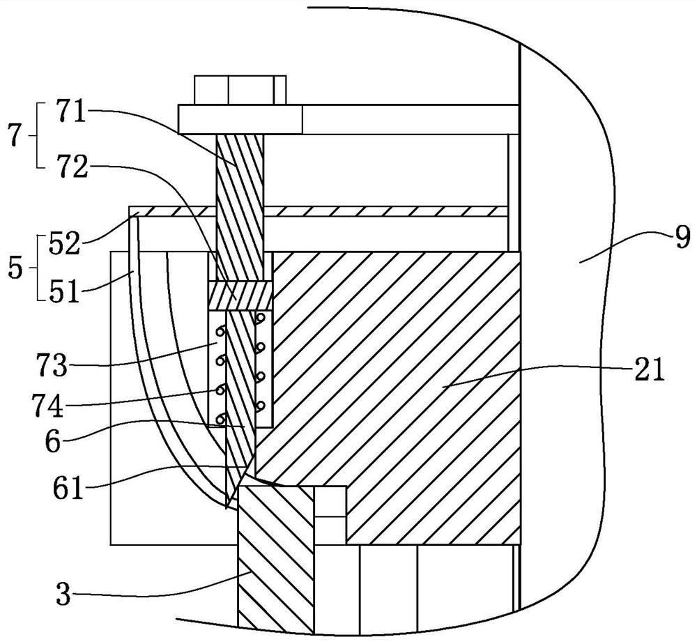
[0066] refer to Figure 5 , a tree transplanting hanger, the difference from Embodiment 1 is that the lower surface of the arc-shaped suspender 21 is provided with a square groove communicating with the guide chute 211, and one end of the extension 5 is connected to the arc-shaped suspender 21 , the other end of the spring 53 connected to the moving block 3, one end of the spring 53 is fixed to the surface of the square groove close to the center line of the arc boom 21, and the other end of the spring 53 is fixed to the surface of the moving block 3 away from its contact with the fixed block 6 , the spring 53 exerts a force on the moving block 3 to make the pressing rod 4 rotate away from the end connected to the moving block 3 and away from the center line of the suspension ring 2 .

[0067] The implementation principle of the above-mentioned embodiment is:

[0068] The spring 53 directly exerts an active force on the moving block 3. When the driving mechanism 7 removes the...

Embodiment 3

[0070] refer to Figure 6 , a tree transplanting hanger, the difference from Embodiment 1 is that the guide chute 211 is a convex-shaped groove spirally arranged along the circumference of the arc-shaped suspender 21. The inner surface of the compression rod is fixed with elastic protective plates, which are not shown in the accompanying drawings, and there is a gap of no more than 10 cm between two adjacent protective plates.


PUM


Abstract

The invention discloses a tree transplanting sling which comprises a lifting rope; a winding rope is connected with one end of the lifting rope; a hoisting and conveying frame is detachably connectedwith the other end of the lifting rope and comprises a hoisting ring; the hoisting ring comprises arc shaped hanger rods detachably connected; the arc shaped hanger rods are sequentially connected endto end to form the hoisting ring; movable blocks are in sliding fit with the arc shaped hanger rods; at least three movable blocks are arranged at intervals in the circumferential direction of the hoisting ring and can move in the central line direction of the hoisting ring; compressing rods are fixedly connected onto the movable blocks; extending pieces capable of driving the movable block to move are connected onto the hoisting ring; fixed blocks in one-to-one correspondence with the movable blocks are arranged on the hoisting ring and are in sliding fit with the hoisting ring; and a driving mechanism applying acting force to the fixed blocks to enable the fixed blocks and the movable blocks to keep compressing connection is arranged on the fixed blocks. The tree transplanting sling hasthe effect of conveniently and efficiently wrapping and protecting the soil ball of the transplanted tree.

Description

technical field [0001] The invention relates to the technical field of tree transplanting equipment, in particular to a tree transplanting hanger. Background technique [0002] In urban greening projects, because it is difficult to cultivate saplings from a young age, trees in forest farms or suburbs are usually transplanted, which greatly speeds up the greening process. However, trees, as a living body, need to be treated with caution during the process of transplanting and hoisting. [0003] The Chinese utility model patent whose authorized notification number is CN205709463U discloses a tree transplanting hanger, including: a suspension frame, which is a triangular pyramid structure, and a vertex of the suspension frame is used to be fixed on the crane, and the suspension frame The other three vertices are suspension points; and three suspension chains, the fixed ends of the three suspension chains are respectively connected to the three suspension points of the suspensio...

Claims


Application Information

Patent Timeline
Patent Type & Authority Applications(China)
IPC IPC(8): B66C1/42B66C13/00
CPCB66C1/42B66C13/00
Inventor 刘鸿飞
Owner 北京胖龙丽景科技有限公司
Why Eureka
Try Eureka