Industrial chemical waste liquid copper recovery device

A technology for recycling equipment and waste liquid, which is applied in the field of industrial chemistry, can solve the problems of low copper recovery rate and small volume, and achieve the effect of avoiding cleaning

Pending Publication Date: 2020-09-01
成都天智佳网络科技有限公司
View PDF7 Cites 4 Cited by
  • Summary
  • Abstract
  • Description
  • Claims
  • Application Information

AI Technical Summary

Benefits of technology

This patented technology allows for efficient cleanup or disposal of harmful materials from industrial processes by producing tiny metal particles with specific properties such as size, shape, density, etc., which help them stick together more easily during solidification after being dissolved into water.

Problems solved by technology

This patented technical problem addressed by this patents relating to an industry's spent solution called Cremation Technologies (CT) was finding it difficult or expensive to recover pure metal from these solutions due to their low efficiency during filtrations caused by residue buildup inside the device walls which cause contamination issues when trying to recycle them back into use again.

Method used


Image

  • Industrial chemical waste liquid copper recovery device
  • Industrial chemical waste liquid copper recovery device
  • Industrial chemical waste liquid copper recovery device

Examples


Embodiment 1

[0027] For example figure 1 -example Figure 5 Shown:

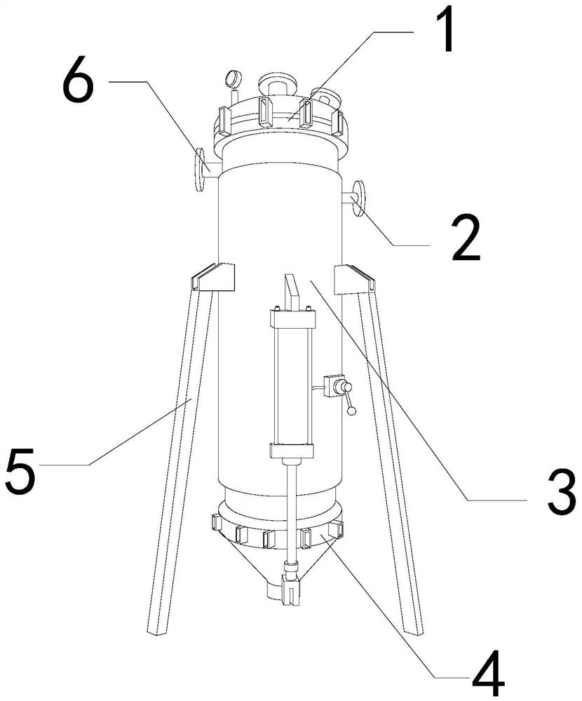
[0028] The invention provides an industrial chemical waste liquid copper recovery equipment, the structure of which includes a top cover 1, a waste liquid inlet 2, a reaction chamber 3, a filter end 4, a bracket 5, and a reaction liquid inlet 6. The waste liquid inlet 2 is installed in the reaction The right side of the chamber 3, the filter end 4 is fixed at the bottom of the reaction chamber 3, the bracket 5 is welded to the reaction chamber 3, the reaction liquid inlet 6 is connected to the internal position of the reaction chamber 3, and the reaction The cavity 3 is embedded in the lower end of the top cover 1 .

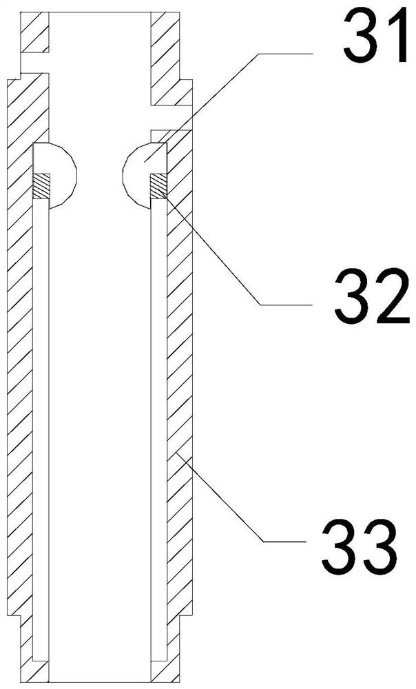
[0029] Wherein, the reaction chamber 3 includes a scraper mechanism 31, a buoyancy block 32, and a frame body 33, the scraper mechanism 31 is matched with the inner wall of the frame body 33, the buoyancy block 32 is embedded and connected with the scraper mechanism 31, The buoyancy block 32 is made of fo...

Embodiment 2

[0036] For example Image 6 -example Figure 8 Shown:

[0037] Wherein, the deformed surface a1 includes a rotating roller c1, a baffle c2, and a board surface c3, the rotating roller c1 is movably engaged with the baffle c2, and the baffle c2 is embedded and fixed on the left and right sides of the board c3, There are seven rotating rollers c1, which are evenly distributed in an arc shape between the two baffles c2, and the rotating roller c1 can be rotated by flowing on the plate surface c3 when the water level inside the mechanism drops.

[0038] Wherein, the rotating roller c1 includes a cleaning surface c11, a movable piece c12, a protective piece c13, and a joint ring c14. The cleaning surface c11 and the movable piece c12 are of an integrated structure, and the movable piece c12 is hinged to the joint ring c14. The protective sheet c13 is installed between two adjacent movable sheets c12, and there are twelve movable sheets c12, which are evenly divided into circular ...


PUM


Abstract

The invention discloses an industrial chemical waste liquid copper recovery device. The device structurally comprises a top cover, a waste liquid inlet, a reaction cavity, a filter end, a support anda reaction fluid inlet, wherein the waste liquid inlet is mounted in the right side of the reaction cavity, the filter end is fixed to the bottom of the reaction cavity, the support and the reaction cavity are welded together, the reaction liquid inlet penetrates through the interior of the reaction cavity, the reaction cavity is embedded and fixed in the lower end of the top cover, by means of abuoyancy block, a scraping mechanism can be driven to synchronously descend along the inner wall of a frame body according to descending of a water level of a waste liquid, so that the scraping mechanism can scrape copper particles attached to the inner wall of the reaction cavity, flow on the surface of a deformation surface is achieved when the waste liquid is discharged, the flowing waste liquid can push a rotating roller on the deformation surface to rotate, so that the flowing waste liquid can wash down copper ions attached to the surface of a board and the surface of the rotating roller,and the situation that the copper ions attached to the deformation surface are not prone to removal is avoided.

Description


Claims


Application Information

Patent Timeline
Owner 成都天智佳网络科技有限公司
Why Eureka
Try Eureka