Reverse osmosis water purifier

A technology for percolating water and leveling, applied in water conservancy projects, waterway systems, sewage removal, etc., can solve problems such as easy blockage of the water filter layer, collapse of the wall, damage to the water filter layer, etc., so as to improve the drainage stability and prevent the wall body collapse effect

Pending Publication Date: 2021-12-17
广州晨创建筑产业有限公司
View PDF0 Cites 0 Cited by
  • Summary
  • Abstract
  • Description
  • Claims
  • Application Information

AI Technical Summary

Problems solved by technology

[0003] Although this method is simple and easy to implement, when gravel or porous concrete blocks are filled at the outlet as the water filter layer, the water filter layer is easily blocked, resulting in the inability to discharge the stagnant water, or rats digging up the gravel to cause filtration When the water layer is destroyed, it will be discharged together with mud and sand during drainage, and the hollowed out mud and sand will cause wall collapse, landslides,

Method used


Image

  • Reverse osmosis water purifier
  • Reverse osmosis water purifier
  • Reverse osmosis water purifier

Examples


Embodiment 1

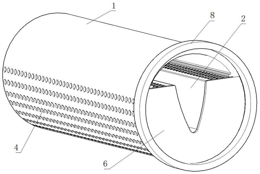
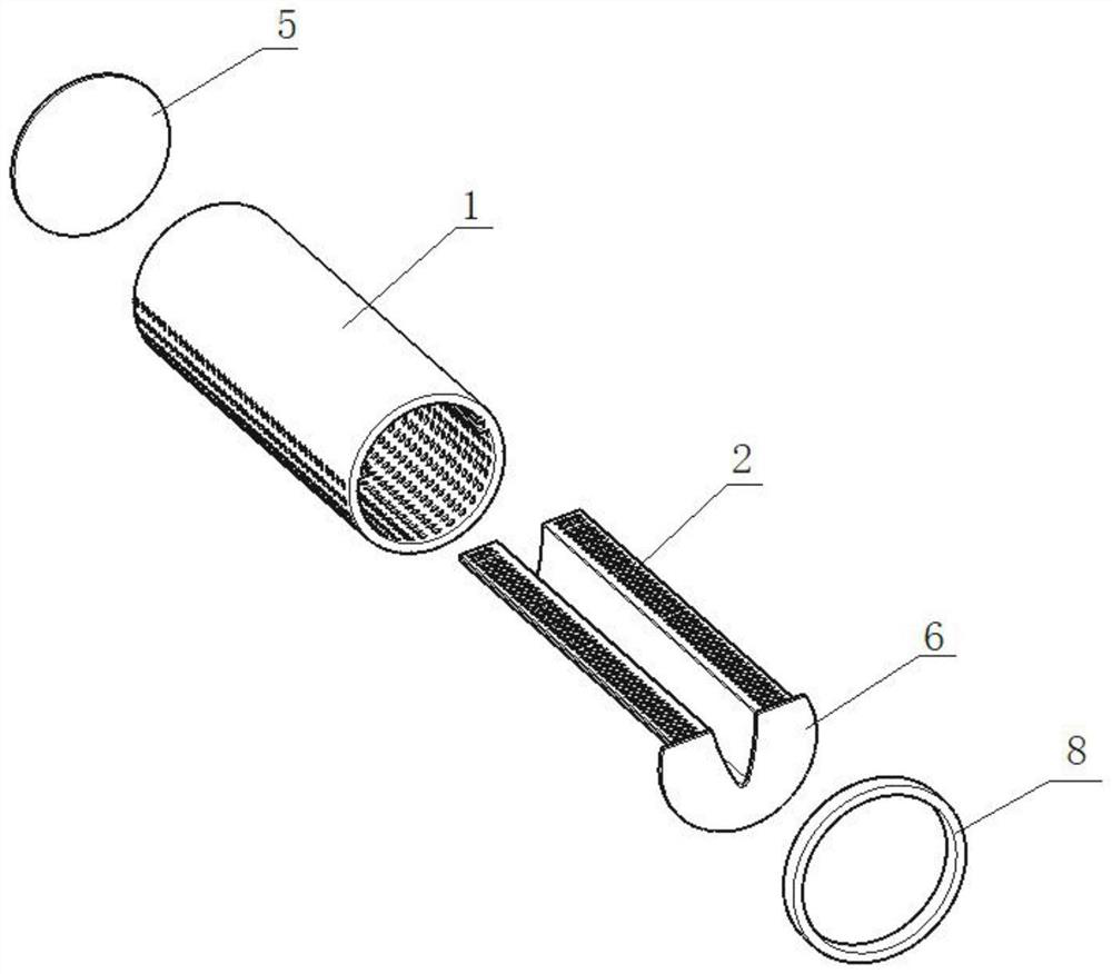
[0026] This embodiment is applicable to the scenario of drainage facilities on retaining walls, such as Figure 1-2 As shown, a reverse osmosis water filter includes a drain pipe 1 and a diverter plate 2 whose length is adapted to the drain pipe 1;

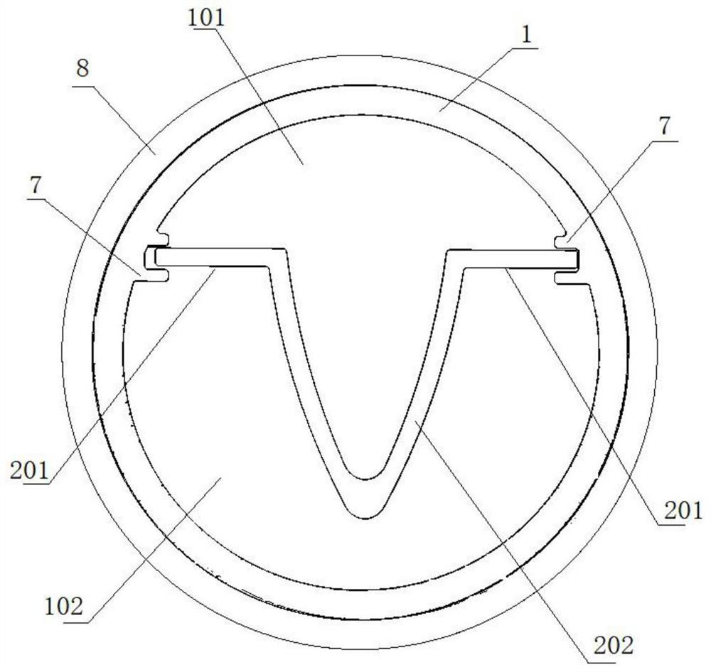
[0027] The splitter plate 2 is horizontally arranged in the drain pipe 1, and the two ends of the splitter plate 2 are connected to the inner wall of the drain pipe 1, and the splitter plate 2 divides the inner cavity of the drain pipe 1 into an upper drain chamber 101 and a lower water accumulation chamber 102;

[0028] A plurality of first filter holes 3 are uniformly arranged on the splitter plate 2;

[0029] A plurality of second filter holes 4 are uniformly provided on the pipe wall of the lower water collecting chamber 102;

[0030] One end of the drain pipe 1 is provided with a first sealing plate 5;

[0031] The other end of the drain pipe 1 is provided with a second sealing plate 6 , and the second sealing plate 6 is pr...

Embodiment 2

[0055] This embodiment is suitable for farmland irrigation scenarios, low-lying water seeps into the reverse osmosis water filter, and when the land is dry and needs to replenish water, pump water from the main outlet of the drainage pipe 1 of the stand-up water filter to flow into each The branch pipe of the reverse osmosis water filter is discharged into the soil, so that the roots of the plants can absorb water, forming a combination of supply and drainage, and avoiding the inconvenience of digging pits on the surface of the land for agricultural machinery.

[0056] Further, the reverse osmosis water filter provided by the present application can be cleaned, and can be reversely flushed from the outside of the water outlet to the inside by a water pump at regular intervals, and the silt will not be washed away due to the blocking of the diverter plate.


PUM


Abstract

The invention relates to the technical field of accumulated water drainage, in particular to a reverse osmosis water purifier. The reverse osmosis water purifier comprises a drainage pipe and a splitter plate, wherein the length of the splitter plate is matched with that of the drainage pipe, the splitter plate is horizontally arranged in the drainage pipe, the two ends of the splitter plate are connected with the inner wall of the drainage pipe, and an inner cavity of the drainage pipe is divided into an upper drainage cavity and a lower water accumulation cavity by the splitter plate; a plurality of first filtering holes are uniformly formed in the splitter plate; a plurality of second filtering holes are uniformly formed in the pipe wall of the lower water accumulation cavity; a first sealing plate is arranged at one end of the drainage pipe; and a second sealing plate is arranged at the other end of the drainage pipe, and a water outlet which corresponds to the upper drainage cavity is formed in the second sealing plate. Accumulated water can be effectively drained, additionally, wall collapse caused by hollowing out silt is prevented, and the drainage stability and the use stability of a retaining wall are improved.

Description

technical field [0001] The invention relates to the technical field of accumulated water discharge, and more specifically, to a reverse osmosis water filter. Background technique [0002] Retaining wall is a common form of slope protection, which is widely used in engineering because of its simple structure, convenient construction and good stability. As we all know, groundwater and surface water are an important factor affecting the stability of the retaining wall. In order to increase the stability of the retaining wall, the retaining wall should be equipped with good drainage facilities to drain the water in the soil behind the wall and prevent the ground Underwater seepage causes water to build up hydrostatic pressure behind the wall. At present, the most commonly used drainage method is to set up a drain on the retaining wall. PVC pipes or bamboo sticks are often used to reserve the drain, and some gravel is backfilled at the drain to filter the sediment in the accumul...

Claims


Application Information

Patent Timeline
IPC IPC(8): E02D29/02E03F1/00
CPCE02D29/02E03F1/00
Inventor 莫志强莫汉锋
Owner 广州晨创建筑产业有限公司
Why Eureka
Try Eureka