Granulator for plastic particle processing

A plastic granule and granulator technology, which is applied in the field of plastic granule processing equipment, can solve the problems of uneven output of plastic granules, plastic entanglement and shredding, and lower yield and quality.

Pending Publication Date: 2021-07-06
梁海林
View PDF8 Cites 0 Cited by
  • Summary
  • Abstract
  • Description
  • Claims
  • Application Information

AI Technical Summary

Problems solved by technology

[0006] Aiming at the deficiencies of the prior art, the present invention provides a granulator for processing plastic granules, which solves the problem that if the input plastic is of a hard materi

Method used


Image

  • Granulator for plastic particle processing
  • Granulator for plastic particle processing
  • Granulator for plastic particle processing

Examples


Embodiment 1

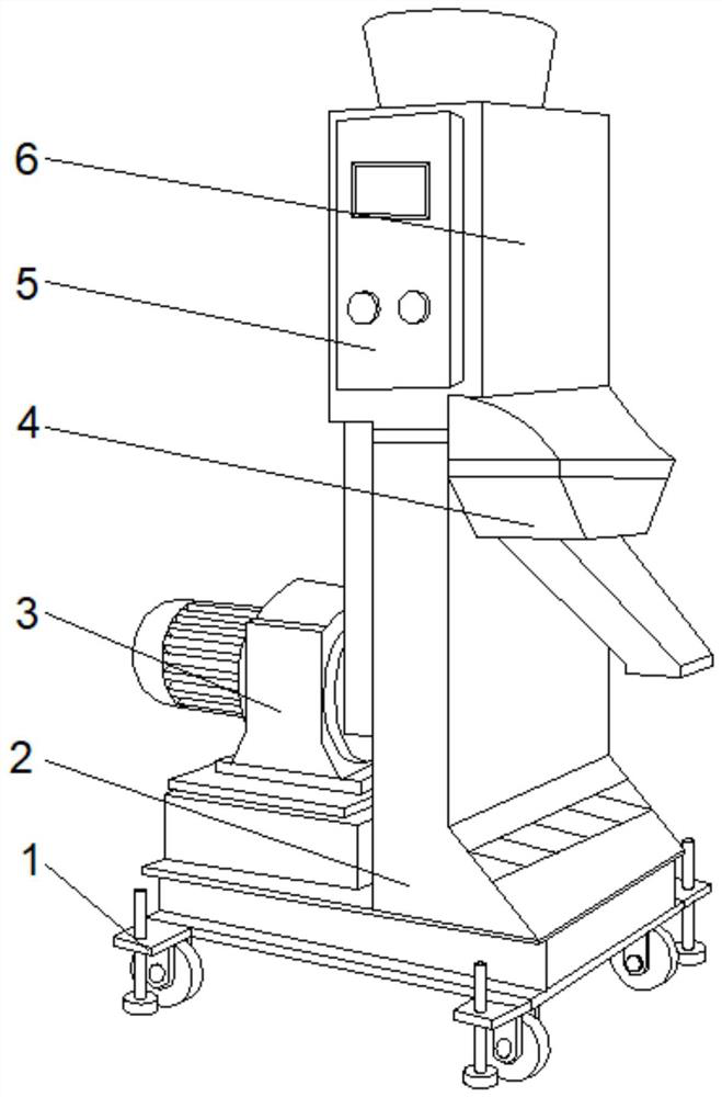
[0035] See Figure 1-2The present invention provides a technical solution: a plastic particle processing plate machine, including the body 2, both sides of the bottom portion of the body 2, fixedly connected to the support seat 1, the left side of the body 2 fixedly connected to the drive 3 The top portion of the body 2 is fixedly connected to the cutting device 6, and the front surface of the cutting device 6 is fixedly connected to the controller 5, and the right side of the body 2 is located at the bottom of the cutting device 6 is provided with a bulk 4.

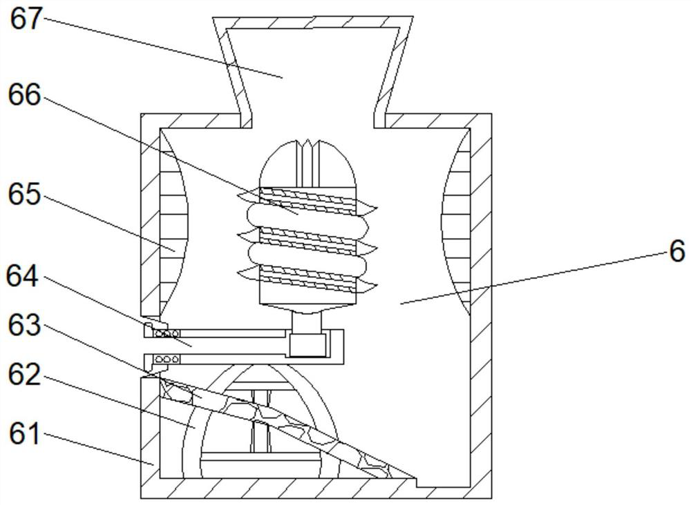
[0036] Wherein, the cutting device 6 includes an outer frame 61, and the top intermediate position of the outer frame 61 is provided with a feed strip 67, and the top of the outer wall of the outer frame 61 is fixedly connected to the block 65, and the outer wall of the outer frame 61 is opened. The groove 64, the rotation groove 64 runs through the outer frame 61 and extends to the inside of the outer frame 61, and the rotat...

Embodiment 2

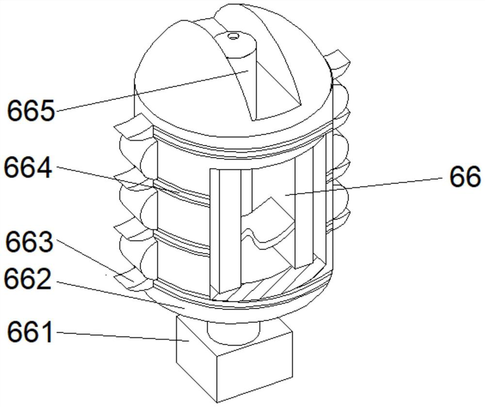
[0039] See Figure 1-4 On the basis of the first example, the present invention provides a technical solution: the cutting mechanism 66 includes a housing 662, and the outermost position of the outer casing 662 is fixedly connected to the connector 661, and the outer surface of the outer casing 662 is opened with a chopper groove 664, housing The outer surface of 661 is fixed to both sides of the chopper groove 664 fixed to the cutter 663, and the top intermediate position of the outer casing 662 is provided with auxiliary mechanism 665, and the bottom portion of the auxiliary mechanism 665 extends through the outer casing 661 and extends inside the outer casing 661.

[0040] Wherein, the auxiliary mechanism 665 includes auxiliary frame D1, and the inner chamber of the secondary cavity of the auxiliary frame D1 is opened, and the intermediate position of the secondary cavity of the auxiliary frame D1 is provided with auxiliary knife D2. The bottom side of the auxiliary knife D2 is ...

Embodiment 3

[0043] See Figure 1-7 In the basis of the first embodiment, the present invention provides a technical solution: the linkage mechanism D6 includes the force plate D61, the middle of the outer wall of the force plate D61 is fixedly connected to the outer mount D66, the force plate The top of the D61 is fixedly connected to the fixing plate D62, and the intermediate position of the lumen bottom of the fixing plate D62 is provided with the squeezing rod D63, and the top portion of the pressing rod D63 penetrates through the fixing plate D62 and extends the outer portion of the fixed plate D63, and the rod D63 is extruded. The top fixedly connected to the external plate D64, and the bottom of the fixing plate D62 is fixed to both sides of the force plate D61 fixed to the elastic strip D65.

[0044] Wherein, the outer pusher D66 includes a push plate T1, and the top of the push plate T1 is fixedly connected to the top rod T3, and the inner cavity of the push plate T1 is fixed to the ca...


PUM


Abstract

The invention discloses a granulator for plastic particle processing. The granulator comprises a machine body; supporting seats are fixedly connected with the two sides of the bottom of the machine body; a driver is fixedly connected with the left side of the bottom of the machine body; a cutting device is fixedly connected with the top of the machine body; a controller is fixedly connected with the top of the front face of the cutting device; and a discharging hopper is arranged at the position, located at the bottom of the cutting device, of the right side of the machine body. The granulator for plastic particle processing relates to the technical field of plastic particle processing equipment. According to the granulator for plastic particle processing, protection of particles is facilitated, the situation of bending or breakage is avoided, the output uniformity of the plastic particles is facilitated, the yield quality of production and processing is effectively improved, small powder particles are further prevented from being adhered to the inner wall of the granulator, the interior of the granulator is well supported in the cutting process, shaking generated by cutting is reduced, and the stability of the granulator is further improved; and a supporting base is divided into rolling wheels and supporting columns, so that the movement of the granulator is facilitated.

Description

Technical field [0001] The present invention relates to the technical field of plastic particle processing equipment, and is specifically a plastic particle processing gritter. Background technique [0002] The plastic is a single body as a raw material, a polymer compound polymerized polymerized by adding or polycondensation, is commonly known as a plastic or resin, and can be freely changing the ingredients and formats, resulting from synthetic resins and fillers, plasticizers, stabilizers, lubricants, An additive such as a color, the main component of the plastic is a resin, and the resin is a polymer compound that has not been mixed with various additives. The basic properties of plastics are mainly determined in the nature of the resin, but the additive also plays an important role, some plastics substantially It is composed of synthetic resins, no or less additives such as organic glass, polystyrene, and the like. [0003] According to a cantilever pelletizer according to C...

Claims


Application Information

Patent Timeline
IPC IPC(8): B29B9/06
CPCB29B9/06
Inventor 梁海林
Owner 梁海林
Why Eureka
Try Eureka