Distributed three-dimensional factory floor slab and manufacturing method

A distributed, floor-slab technology, applied in floors, building components, buildings, etc., can solve the problems of high assembly cost, unfavorable overall performance, insufficient rigidity, etc., to save the investment and transportation costs of prefabricated plants, and save investment and transportation and hoisting costs. , The effect of improving the performance of shock absorption, sound insulation and thermal insulation

Inactive Publication Date: 2020-09-01
黄通
View PDF14 Cites 2 Cited by
  • Summary
  • Abstract
  • Description
  • Claims
  • Application Information

AI Technical Summary

Problems solved by technology

But the laminated board also has its shortcomings. 1. In order to meet the requirements of installation rigidity and splicing structure integrity, the end face of the laminated board needs to protrude from the beard tendon of the laminated board, and the beard tendon occupies the transportation and storage space of the laminated board. , increase the transportation cost, the manufacturing precision of the beard tendons is poor, and there is mutual interference during installation; 2. After the operation is completed, the stiffness distribution of the whole laminated board along the two directions is not uniform, which is not conducive to the overall performance of the board; 3. Due to the The floor slab is composed of the prefabricated floor part and the cast-in-place part of the laminated layer. There is a difference in the age of the two parts of the concrete, so there will be a difference in the shrinkage stress. When the age difference between the two parts is greater, the difference in shrinkage stress The larger the slab, the shear problem of the interface between the prefabricated part and the cast-in-place part exists; 4. The thermal insulation and shock absorption effect of the laminated slab is poor; Part of the mid-span deflection is too large when bearing construction loads; the cost of transportation, hoisting and assembly of 6 laminated panels is high, joints need additional reinforcement, and production stacking occupies a large area

Method used


Image

  • Distributed three-dimensional factory floor slab and manufacturing method
  • Distributed three-dimensional factory floor slab and manufacturing method
  • Distributed three-dimensional factory floor slab and manufacturing method

Examples


Embodiment Construction

[0026] The following will clearly and completely describe the technical solutions in the embodiments of the present invention with reference to the accompanying drawings in the embodiments of the present invention. Obviously, the described embodiments are only some, not all, embodiments of the present invention. Based on the embodiments of the present invention, all other embodiments obtained by persons of ordinary skill in the art without making creative efforts belong to the protection scope of the present invention.

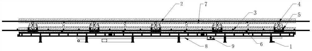
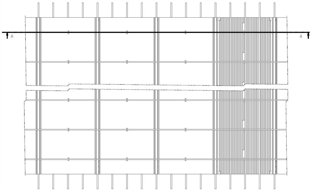
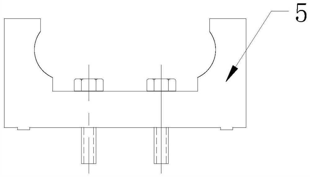
[0027] see Figure 1-4 , the present invention provides a technical solution: a distributed three-dimensional factory floor, including double-T formwork 1, steel bars 2, steel mesh sheets 3, steel plate cold-extruded trusses 4, truss clips 5, pads 6 , Inorganic thermal insulation, sound insulation and fire prevention floor cavity 7, water and electricity heating network pipe 8, threading box 9, the outside of the inorganic thermal insulation, sound insulation ...


PUM


Abstract

The invention relates to the technical field of building materials, and discloses a distributed three-dimensional factory floor slab and a manufacturing method. The distributed three-dimensional factory floor slab comprises non-dismantling concrete bundle heat preservation double-T formworks, steel bars, steel bar meshes, steel plate cold-extruded trusses, truss clamping parts, cushion blocks, inorganic heat preservation, sound insulation and fireproof floor slab cavities, water-electricity-heating network pipes and threading boxes, wherein high-performance concrete is poured outside the inorganic heat preservation, sound insulation and fireproof floor slab cavities. The distributed three-dimensional factory floor slab disclosed by the invention does not need the links of PC fabrication, transportation and hoisting, saves the PC factory investment, transportation and hoisting cost, and does not need to solve the structural problem of mounting abutted seams. According to the floor slab,floor-after-floor operation is carried out, so that the floor area is saved. The floor slab is provided with the steel bar meshes and the steel plate cold-extruded trusses, so that large-span mounting can be realized. A bottom formwork of the floor slab is of a hollow structure, so that the floor slab has sound insulation, sound absorption and heat preservation functions, and is light in mass andconvenient for transportation and hoisting. The inorganic heat preservation, sound insulation and fireproof floor slab cavities are paved in the middle of the floor slab, so that the dead weight of the floor slab is reduced by 30 to 60 percent.

Description

technical field [0001] The invention relates to the technical field of building materials, in particular to a distributed three-dimensional factory floor and a preparation method. Background technique [0002] With the continuous development of industrialization, laminated floors combined with the advantages of prefabricated floors and cast-in-place floors have been widely used. But the laminated board also has its shortcomings. 1. In order to meet the requirements of installation rigidity and splicing structure integrity, the end face of the laminated board needs to protrude from the beard tendon of the laminated board, and the beard tendon occupies the transportation and storage space of the laminated board. , increase the transportation cost, the manufacturing precision of the beard tendons is poor, and there is mutual interference during installation; 2. After the operation is completed, the stiffness distribution of the whole laminated board along the two directions is ...

Claims


Application Information

Patent Timeline
Patent Type & Authority Applications(China)
IPC IPC(8): E04B5/00E04B5/48E04B5/43C04B28/02C04B28/04C04B111/28C04B111/52
CPCC04B28/02C04B28/04C04B2111/28C04B2111/52E04B5/00E04B5/43E04B5/48C04B18/08C04B18/146C04B2103/0068C04B14/06
Inventor 黄书亮黄振举王秀杰张纪会王忠民
Owner 黄通
Why Eureka
Try Eureka