Production testing device and method for non-full-tube flowmeter

A technology for producing testing and flow meters, which is applied in the direction of testing/calibrating devices, measuring devices, testing/calibrating volume flow, etc. It can solve problems such as inaccurate results and achieve the effect of improving detection efficiency and improving the level of detection automation

Pending Publication Date: 2020-09-01
四川中大华瑞能源技术有限公司
View PDF0 Cites 2 Cited by
  • Summary
  • Abstract
  • Description
  • Claims
  • Application Information

AI Technical Summary

Problems solved by technology

[0003] At present, most of the electromagnetic flowmeters on the market can only be used for the flow measurement of the full pipe. For the fluid that is not full of the pipe or the fluid is in the conversion process between the full pipe and the non-full pipe, because the cross-sectional area of ​​the fluid in the pipe is no longer the measurement The cross-sectional area of ​​the pipe, the result obtained by the traditional flowmeter is inaccurate, so the detection method of the partial pipe flowmeter needs to consider the two parameters of the average flow velocity and liquid level height of the fluid in the measurement pipe, and then calibrate it

Method used


Image

  • Production testing device and method for non-full-tube flowmeter
  • Production testing device and method for non-full-tube flowmeter
  • Production testing device and method for non-full-tube flowmeter

Examples


Embodiment 1

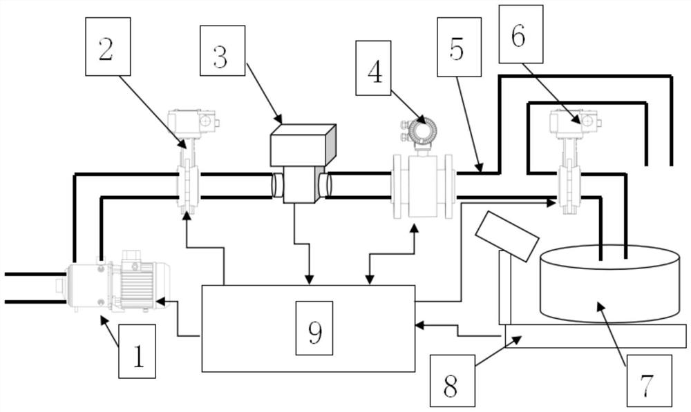
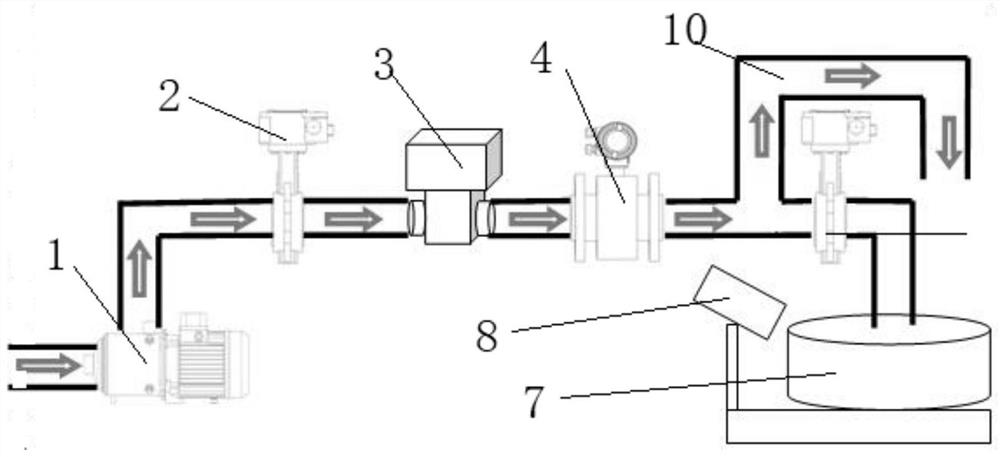
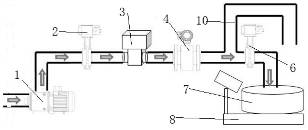
[0034] Such as figure 1 As shown, the part-filled pipe flowmeter production test device includes a measuring channel arranged horizontally, and one end of the measuring channel is connected to a water supply device, and the water supply device includes a water pump 1, and the input end of the water pump 1 is connected to the The water source is connected, the output end of the water pump 1 is connected with the first electric valve 2, and the height of the water pump 1 is lower than the measuring channel.

[0035] The water outlet end of the first electric valve 2 is connected with a flowmeter standard meter 3; the flowmeter standard meter 3 is connected with the partial pipe flowmeter 4 to be tested, and the front end of the partial pipe flowmeter 4 is connected with a flow meter Meter standard table 3; the back end of the part-filled pipe flowmeter 4 is connected with a flowmeter outlet measuring pipe 5, and the back end of the flowmeter outlet measuring pipe 5 is connected ...

Embodiment 2

[0046] The present invention also discloses a test method based on a partial pipe flowmeter production test device, comprising the following steps:

[0047] 1. First, calibrate the empty pipe parameters of the flowmeter when the pipe is dry;

[0048] 2. In the case of water flow, open the first electric valve 2, and when water enters the measuring cylinder 7, immediately close the water pump 1 and the first electric valve 2, so that the water fills the entire pipe of the partially filled pipe flowmeter 4, and then Carry out zero calibration when the water is still;

[0049] 3. Measure the full-scale calibration of the part-full pipe flowmeter 4 when the pipe is full; after the reading of the electronic platform scale 8 is reset to zero, open the first electric valve 2, start the water pump 1, and adjust the first electric valve 2 to make the flow rate reach The full-scale value of the part-full pipe flowmeter 4, the liquid passing through the part-full pipe flowmeter 4 is fin...


PUM


Abstract

The invention discloses a production testing device and method for a non-full-tube flowmeter. The device comprises a measurement channel which is horizontally arranged, one end of the measurement channel is connected with a water supply device, the other end of the measurement channel is connected with a measurement device, and the measurement device comprises a liquid volume measurement device and a liquid weight measurement device. The water supply device is used for providing water in the testing process and ensuring the constant water pressure; the measurement channel is horizontally arranged, so that the stability of the water flow is ensured, and problems of inaccurate measurement and test failure caused by water flow fluctuation and wave generation are solved. The measurement devicecan adopt both volume measurement and weight measurement, the volume measurement is convenient for a measurer to directly read the number, and the weight measurement is convenient for realizing automatic result output.

Description

technical field [0001] The invention relates to the field of flowmeter detection, in particular to a production and testing device and method for a partially filled pipe flowmeter. Background technique [0002] Electromagnetic flowmeter is a kind of velocity flowmeter, which is an instrument for measuring the flow rate of conductive fluid by electromagnetic induction method. The principle is to place the magnetic field in a direction perpendicular to the flow of the fluid. When the conductive fluid passes through, an induced potential is generated due to the fluid cutting the magnetic force line, and the induced potential is drawn out by two electrodes. When the magnetic field strength is constant and the pipe diameter is constant, the magnitude of the induced potential is only related to the flow velocity of the fluid, and the flow value can be determined by converting the induction signal into the flow velocity. Its advantage is that there are no moving parts in the measu...

Claims


Application Information

Patent Timeline
Patent Type & Authority Applications(China)
IPC IPC(8): G01F25/00
CPCG01F25/10G01F25/14
Inventor 蒋小春
Owner 四川中大华瑞能源技术有限公司
Why Eureka
Try Eureka