Anti-rotation optical fiber contact element capable of being taken out later and sent later and operation method

An optical fiber contact and anti-rotation technology, applied in optical components, light guides, optics, etc., can solve the problems of high operation difficulty, increased pin loss of optical fiber contacts, and difficulty in ensuring the performance and reliability of optical fiber connectors. To achieve the effect of convenient operation and ensure stability

Pending Publication Date: 2020-09-01
西安光谷光电科技有限责任公司
View PDF0 Cites 0 Cited by
  • Summary
  • Abstract
  • Description
  • Claims
  • Application Information

AI Technical Summary

Problems solved by technology

However, because there is no anti-rotation between the tail handle of the optical fiber contact and the insulator of the optical fiber connector, the situation that the optical fiber contact rotates in the insulator occurs from time to time, which increases the pressure on the contact pin of the optical fiber contact. The loss of the fiber optic connector makes it difficult to guarantee the performance and reliability of the fiber optic connector; it is difficult to install the ferrule in the connector, and it is difficult to ensure that the performance index does not change before and after loading; When there is a problem or fault with the optical fiber contact of a certain channel, it is necessary to take out the entire connector for analysis or replace the entire connector, which seriously affects the working cycle and efficiency of the whole machine

Method used

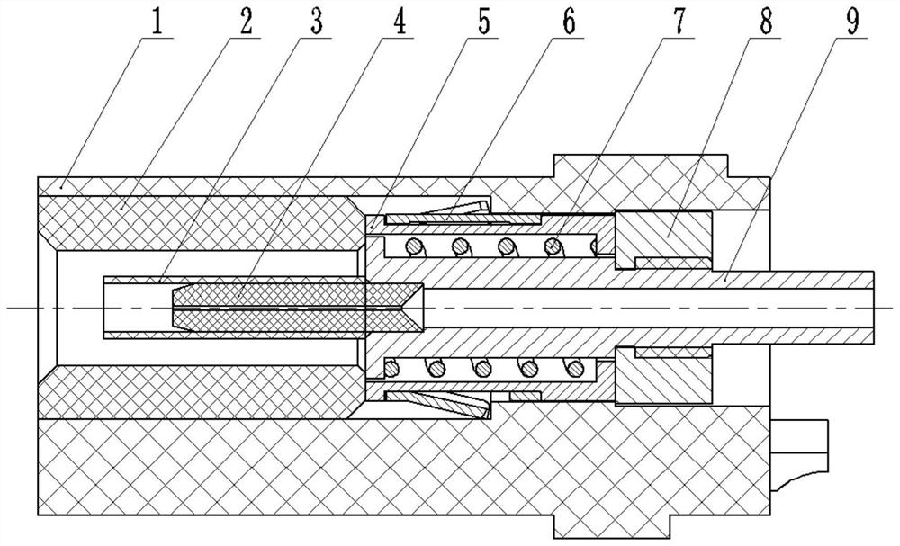

Image

  • Anti-rotation optical fiber contact element capable of being taken out later and sent later and operation method
  • Anti-rotation optical fiber contact element capable of being taken out later and sent later and operation method
  • Anti-rotation optical fiber contact element capable of being taken out later and sent later and operation method

Examples


Embodiment Construction

[0026] In order to make the purpose, technical solutions and advantages of the embodiments of the present invention clearer, the technical solutions in the embodiments of the present invention will be clearly and completely described below in conjunction with the drawings in the embodiments of the present invention. Obviously, the described embodiments It is a part of embodiments of the present invention, but not all embodiments. The components of the embodiments of the invention generally described and illustrated in the figures herein may be arranged and designed in a variety of different configurations.

[0027] Accordingly, the following detailed description of the embodiments of the invention provided in the accompanying drawings is not intended to limit the scope of the claimed invention, but merely represents selected embodiments of the invention. Based on the embodiments of the present invention, all other embodiments obtained by persons of ordinary skill in the art wi...


PUM


Abstract

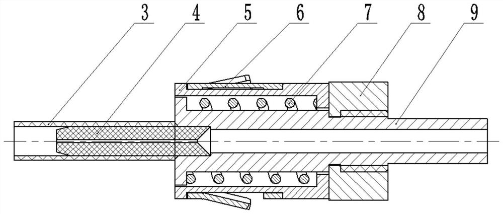
The invention particularly discloses an anti-rotation optical fiber contact element capable of being taken out later and sent later. The device comprises a ceramic ferrule, a ceramic sleeve and a tailhandle; the ceramic ferrule and the ceramic sleeve are coaxially arranged at the front end of the tail handle; the ceramic ferrule is arranged in the ceramic sleeve; the outer side of the tail handleis sleeved with the circular sleeve; a spring is arranged between the inner surface of the circular sleeve and the outer surface of the tail handle; and a pawl spring is arranged on the outer surfaceof the circular sleeve. The anti-rotation optical fiber contact element capable of being taken out later and sent later can be integrated into a connector base, and the requirement for simultaneous transmission of multiple paths of high-precision optical fiber signals can be met.

Description

technical field [0001] The invention belongs to the technical field of high-density multi-core optical fiber connectors for optical signal transmission connectors, and in particular relates to an anti-rotation optical fiber contact piece and an operation method for taking out after delivery. Background technique [0002] The fiber optic contact is the core part of the fiber optic connector. The reliability of the fiber optic contact directly affects the performance of the fiber optic connector and the optical connection. At present, the tail end of the fiber optic contact ferrule on the market is mostly fixed in a tail handle. , the front end of the tail handle has a flange, the rear end of the tail handle is provided with a spring support, and a buffer spring is provided between the flange and the spring support; when in use, the optical fiber contact is assembled on the corresponding optical fiber connector In the insulator of the fiber optic connector, the spring suppor...

Claims


Application Information

Patent Timeline
Patent Type & Authority Applications(China)
IPC IPC(8): G02B6/38
CPCG02B6/3821G02B6/3869G02B6/3887
Inventor 杨伟东魏丹鹏徐启禄史丹昭
Owner 西安光谷光电科技有限责任公司
Why Eureka
Try Eureka