Adjustment system and method for display device in optical module

A technology for display devices and optical modules, applied in optical components, optics, instruments, etc., can solve problems such as being unsuitable for batch display device assembly, production, imperfect assembly and adjustment processes and tools, and increased production costs. The effect of realizing the automation of assembly and adjustment and improving the efficiency of assembly and adjustment according to the needs of mass production

Pending Publication Date: 2020-09-01
弗提图德萨沃有限公司
View PDF0 Cites 6 Cited by
  • Summary
  • Abstract
  • Description
  • Claims
  • Application Information

AI Technical Summary

Problems solved by technology

[0005] At present, the assembly process and tools for display devices in optical modules in the AR and VR industries are not perfect. figure 1 As shown in the display device 03, the traditional assembly and adjustment process usually uses an alignment instrument to first align and debug the light-emitting surface of the opaque display panel 031, and the display panel 031 needs to be characterized on the surface, and the display panel 031 needs to be temporarily Fix; then align and debug the lens or lens assembly so that the op

Method used


Image

  • Adjustment system and method for display device in optical module
  • Adjustment system and method for display device in optical module
  • Adjustment system and method for display device in optical module

Examples


Embodiment 1

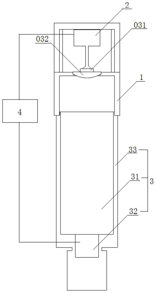
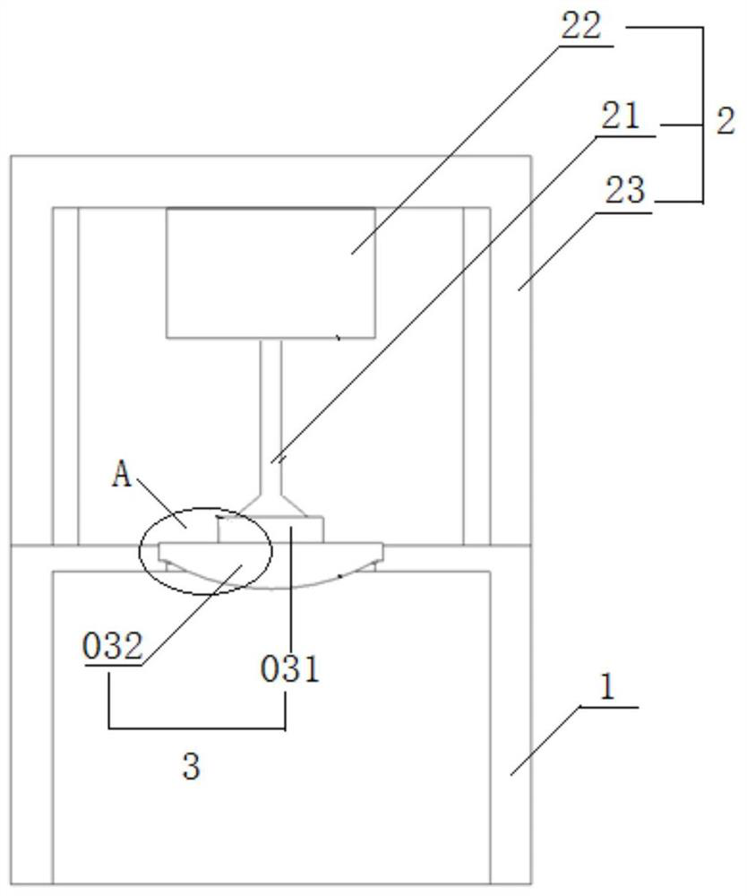
[0064] Figure 2A It is a structural example of the display device installation and adjustment system in the optical module of the present invention. Such as Figure 2A As shown, the assembly and adjustment system of the display device in the optical module includes an alignment fixture 1, an adjustment mechanism 2 and an image acquisition device 3, wherein:

[0065] Alignment jig 1 is used for precise clamping of planar convex lens 032, image 3 In the shown embodiment, the alignment fixture 1 is a hollow structure provided with a chamber 11, and the upper part is provided with a through groove 12 communicating with the chamber 11, and the two side walls of the through groove 12 are provided with holes for clamping a plane convex lens 032. benchmark bit, Figure 2C In the shown embodiment, the concave reference inner step 13 on the upper part of the two side walls of the through groove 12 matches the reference outer step 0321 provided on the outer edge of the planar convex...

Embodiment 2

[0072] Such as Figure 2A As shown, on the basis of Embodiment 1, a processor 4 is added, and the data output interfaces of the camera 32 are all connected to the processor 4, and the camera 32 transmits the alignment image of the display panel 031 captured to the processor 4 for processing and display. , the calculated center of gravity offset and angle offset between the actual position of the display panel 031 and the target position are displayed in any one or more forms of text, graphics, icons, voice prompts, etc., saving the operator from observing, The calculation and conversion time further improves the efficiency.

[0073] Preferably, the data output interface of the driving mechanism of the adjustment platform 22 is connected to the processor 4, and the processor 4 generates a control instruction according to the center of gravity offset and the angular offset between the actual position of the display panel 031 and the target position obtained, and sends it to The...


PUM


Abstract

The invention provides an adjustment system and method for a display device in an optical module; the system is provided with an alignment clamp on a reference position and used for clamping a lens ora lens assembly, an adjusting mechanism is used for adjusting the position of a display panel, and the image acquisition device is used for shooting an alignment image of the display panel. The center offset and the angle offset of the actual position and the target position corresponding to the alignment image of the display panel are obtained, the position of the display panel is adjusted through the adjusting mechanism, and therefore the display panel is fixed to the lens or the lens assembly according to the design requirement. By arranging the reference position for clamping the lens orthe lens assembly, the lens or the lens assembly does not need to be calibrated, a temporary fixing mechanism does not need to be assembled and disassembled, only the position of the display panel needs to be adjusted, operation steps are simplified, and assembling and adjusting efficiency is improved; the operating arm of the adjusting mechanism is of a telescopic structure and is provided with an elastic end, so that the production cost and the operation complexity of the tool are simplified, the adjustment precision is improved, and the mass production requirement is met.

Description

technical field [0001] The invention relates to a technology for installing and adjusting optical components in an optical module, in particular to a system and method for installing and adjusting a display device in an optical module. Background technique [0002] Modern computer technology, display technology, sensor technology and other scientific technologies have promoted the development of AR (Augmented Reality, referred to as Augmented Reality) and VR (Virtual Reality, referred to as Virtual Reality) experience systems. VR scenes create a multi-dimensional information space. The virtual information environment enables users to have an immersive sense of immersion and has a perfect interaction ability with the environment; the AR scene applies virtual information to the real world, and the real environment and the virtual environment are superimposed on the same screen or space in real time simultaneously exist. [0003] The principle of AR and VR display devices is t...

Claims


Application Information

Patent Timeline
IPC IPC(8): G02B27/62G02B27/01
CPCG02B27/0101G02B27/0172G02B27/62
Inventor 不公告发明人
Owner 弗提图德萨沃有限公司
Why Eureka
Try Eureka