Dispensing time control device

A technology of time control and glue dispensing, which is applied to the device and coating of the surface coating liquid, which can solve the problems of long vacant time, glue opening, poor product pressing, etc., and achieve the effect of improving product production capacity

Inactive Publication Date: 2020-09-04
安徽英力电子科技股份有限公司
View PDF7 Cites 1 Cited by
  • Summary
  • Abstract
  • Description
  • Claims
  • Application Information

AI Technical Summary

Problems solved by technology

[0003] In order to solve the problem of poor product pressing or glue opening caused by the product being idle for too long after dispensing, the invention provides a dispensing time control device

Method used


Image

  • Dispensing time control device
  • Dispensing time control device
  • Dispensing time control device

Examples


Embodiment Construction

[0023] The following will clearly and completely describe the technical solutions in the embodiments of the present invention with reference to the accompanying drawings in the embodiments of the present invention. Obviously, the described embodiments are only part of the embodiments of the present invention, not all of them. Based on the embodiments of the present invention, all other embodiments obtained by persons of ordinary skill in the art without making creative efforts belong to the protection scope of the present invention.

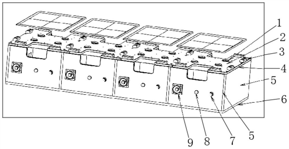
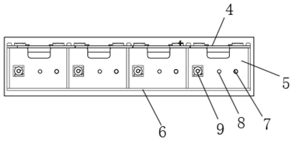
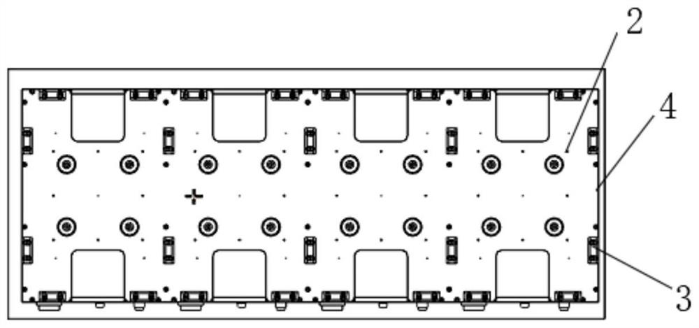
[0024] see Figure 1-5 As shown, a dispensing time control device includes a base plate 6 and a support plate 5 distributed around the base plate, the support plate 5 is fixedly connected with a working table 4, and the working table 4 is provided with four table tops vacancy, the product positioning device 3 for positioning the product is installed on the worktable 4, and the connection mode between the product positioning device 3 and the workt...


PUM


Abstract

The invention discloses a dispensing time control device. The dispensing time control device comprises a bottom plate and supporting plates distributed on the periphery of the bottom plate. A workbench plate is fixedly connected to the supporting plates. A photoelectric sensor is arranged on the workbench plate. When a product is placed on the workbench plate, the photoelectric sensor sends a sensed signal to a timer, and the timer starts timing after receiving the signal. When the product is taken away at the set time, the photoelectric sensor sends a time zero clearing signal to the timer, the time on the timer is cleared, and meanwhile the next time of product timing is started. When the product is not taken away at the set time, the timer sends a signal to a vacuum module and a buzzer.After the vacuum module and the buzzer receive the signals, the buzzer gives an alarm, a vacuum die locks the product, and the product cannot be taken out by the next station. The problem that due tothe fact that the idle time of the product after dispensing is too long, product press fit is poor or glue failure occurs is solved, and the idle time of the product does not need to be calculated manually.

Description

technical field [0001] The invention relates to the technical field of 3C casing production and processing, in particular to a glue dispensing time control device. Background technique [0002] In notebooks and tablet computers, more and more metal components are used. It is difficult to realize the ultra-thin and ultra-light features of electronic products only with structures and buckles in assembly. The structural design is becoming more and more Many use adhesives (such as 14167-NC) to achieve no gaps and a flat and thin appearance. The main operation step of the adhesive is to apply the glue on the metal surface, and then usually a special pressing machine makes the products of the two structures bond together. Due to the vacant time, the adhesive (14167-NC) must be heated and pressed within 2 minutes. If the time exceeds this time, it will easily cause false bonding, affect the final strength, and even cause the phenomenon of product peeling. In the prior art, the b...

Claims


Application Information

Patent Timeline
IPC IPC(8): B05C5/02B05C11/10
CPCB05C5/02B05C11/10
Inventor 李浩余炜韩金方邵继坤王汝欣
Owner 安徽英力电子科技股份有限公司
Why Eureka
Try Eureka