
Precision machining jig

A technology of precision machinery and jigs, which is applied in the field of precision machining jigs and equipment, can solve the problems of reduced operating speed, inability to test the temperature distribution of mobile phone equipment, and reduce the experience of mobile phone equipment, achieving the effect of simple structure

Inactive Publication Date: 2020-09-04
宋鹏威
View PDF0 Cites 2 Cited by
  • Summary
  • Abstract
  • Description
  • Claims
  • Application Information

AI Technical Summary

Problems solved by technology

[0002] In the existing equipment, there are many shortcomings. Because the general test fixtures for mobile phones often use multi-touch testing for the mobile phone screen, but few of the existing equipment are performing multi-touch and simulation. When the personnel use the mobile phone to test the temperature of the mobile phone, due to the difference in the use time of the mobile phone and the temperature generated when the personnel hold the mobile phone, the temperature of the device itself will also be different. As the temperature of the mobile phone device increases, it will make the mobile phone itself Due to the reduction of the operating speed of the mobile phone device, the experience of using the mobile phone device will be greatly reduced, and the mobile phone device must be stopped to cool down. The existing equipment cannot test the temperature distribution of the mobile phone device. , and in the actual test, it is impossible to simulate the situation of people using mobile phones with their hands

Method used


Image

  • Precision machining jig
  • Precision machining jig
  • Precision machining jig

Examples


Embodiment Construction

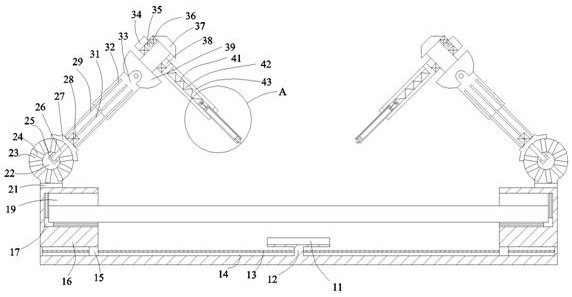
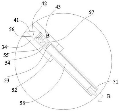
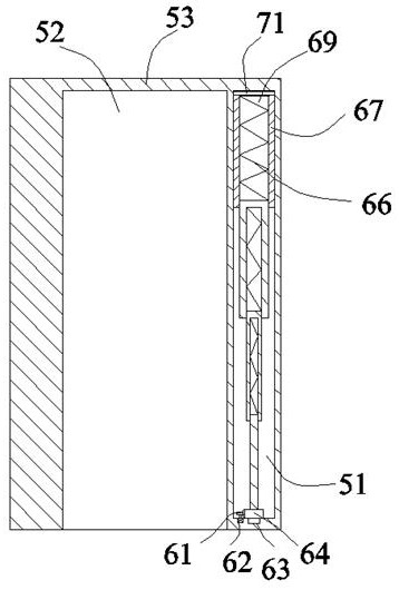
[0025] Such as Figure 1-Figure 4 As shown, the present invention is described in detail. For the convenience of description, the orientations mentioned below are now stipulated as follows: figure 1 The up, down, left, right, front and back directions of the projection relationship itself are consistent. A precision machining tool of the present invention includes a bottom box 12. A symmetrical and open bottom groove 14 is arranged inside the bottom box 12. On the bottom box 12, A scanning detector 11 is fixed on the end face, and a symmetrical top block 16 is arranged on the upper side of the bottom box body 12, and the top block 16 that can make both sides Drive devices that are close to or far away from each other. The top block 16 is provided with a hand-held device that can hold a mobile phone and simulate temperature changes when the person holds it. of simulated mobile devices.

[0026] Beneficially, wherein, the driving device includes a rotating mating threaded rod ...


PUM


Abstract

The invention discloses a precision machining jig. The precision machining jig comprises a bottom box body, symmetrical bottom grooves with openings are formed in the bottom box body, a scanning detector is fixedly arranged on the upper end face of the bottom box body, and symmetrical top blocks are arranged on the upper side of the bottom box body. A driving device capable of enabling the top blocks on the two sides to be close to or away from each other is arranged between the top blocks and the bottom box body, handheld devices capable of clamping mobile phones and simulating temperature changes when people hold the mobile phones by hand are arranged in the top blocks, and simulation moving devices for simulating the use of mobile phone screens by people in a touch mode are arranged onthe upper sides of the top blocks. The equipment is simple in structure, the precision machinery aiming at the mobile phone equipment is adopted, so that the influence of mobile phone screen swiping on the internal temperature of the mobile phones within a certain time when people use the mobile phones in daily life is simulated, and the whole temperature distribution of the mobile phones can be detected and recorded by utilizing the jig.

Description

technical field [0001] The invention relates to the technical field of precision machining jig equipment, in particular to a precision machining jig. Background technique [0002] In the existing equipment, there are many shortcomings. Because the general test fixtures for mobile phones often use multi-touch testing for the mobile phone screen, but few of the existing equipment are performing multi-touch and simulation. When the personnel use the mobile phone to test the temperature of the mobile phone, due to the difference in the use time of the mobile phone and the temperature generated when the personnel hold the mobile phone, the temperature of the device itself will also be different. As the temperature of the mobile phone device increases, it will make the mobile phone itself Due to the reduction of the operating speed of the mobile phone device, the experience of using the mobile phone device will be greatly reduced, and the mobile phone device must be stopped to coo...

Claims


Application Information

Patent Timeline
IPC IPC(8): B25B11/00
CPCB25B11/00
Inventor 宋鹏威
Owner 宋鹏威
Learn More