Automatic positioning and trimming equipment

An automatic positioning and trimming technology, used in household components, other household appliances, household appliances, etc., can solve the problems of low port trimming efficiency, plastic port knife marks, and high trimming efficiency, saving labor costs and repairing. High edge efficiency and good cutting effect

Inactive Publication Date: 2020-09-04
周炜
View PDF7 Cites 0 Cited by
  • Summary
  • Abstract
  • Description
  • Claims
  • Application Information

AI Technical Summary

Problems solved by technology

[0005] The purpose of the present invention is to address the deficiencies of the prior art and provide an automatic positioning and trimming device. The trimming mechanism and the support mechanism are synchronously transmitted through the trimming channel and the upper and lower positions correspond to each other. The positioning components are in the process of side transmission. The positioning and fixing of the plastic parts on the support mechanism is completed, and then by setting the trimming component, the trimming component is used to quickly complete the trimming of the port of the plastic part during the transmission process. The whole action is carried out continuously during the transmission process. The trimming efficiency of plastic parts is high, which solves the problems of low trimming efficiency of plastic parts ports, poor trimming quality, serious knife marks on plastic parts ports and labor-consuming problems of existing equipment

Method used


Image

  • Automatic positioning and trimming equipment
  • Automatic positioning and trimming equipment
  • Automatic positioning and trimming equipment

Examples


Embodiment 1

[0036] Embodiments of the present invention are described in detail below, examples of which are shown in the drawings, wherein the same or similar reference numerals designate the same or similar elements or elements having the same or similar functions throughout. The embodiments described below by referring to the figures are exemplary and are intended to explain the present invention and should not be construed as limiting the present invention.

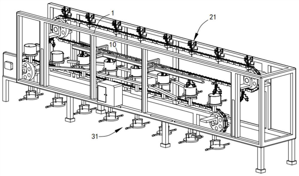
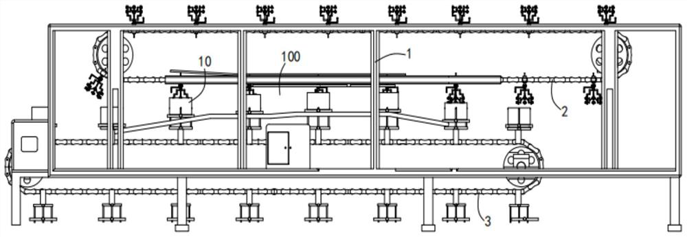
[0037] Such as Figure 1 to Figure 9 As shown, an automatic positioning and trimming equipment includes a frame 1 and a first rotary chain 2 and a second rotary chain 3 arranged on the frame 1, and the first rotary chain 2 and the second rotary chain 3 are arranged up and down , the first rotary chain 2 is provided with a number of trimming mechanisms 21 in an array, and the second rotary chain 3 is provided with a number of support mechanisms 31 in an array;

[0038] A trimming channel 100 is formed between the first rotary cha...

Embodiment 2

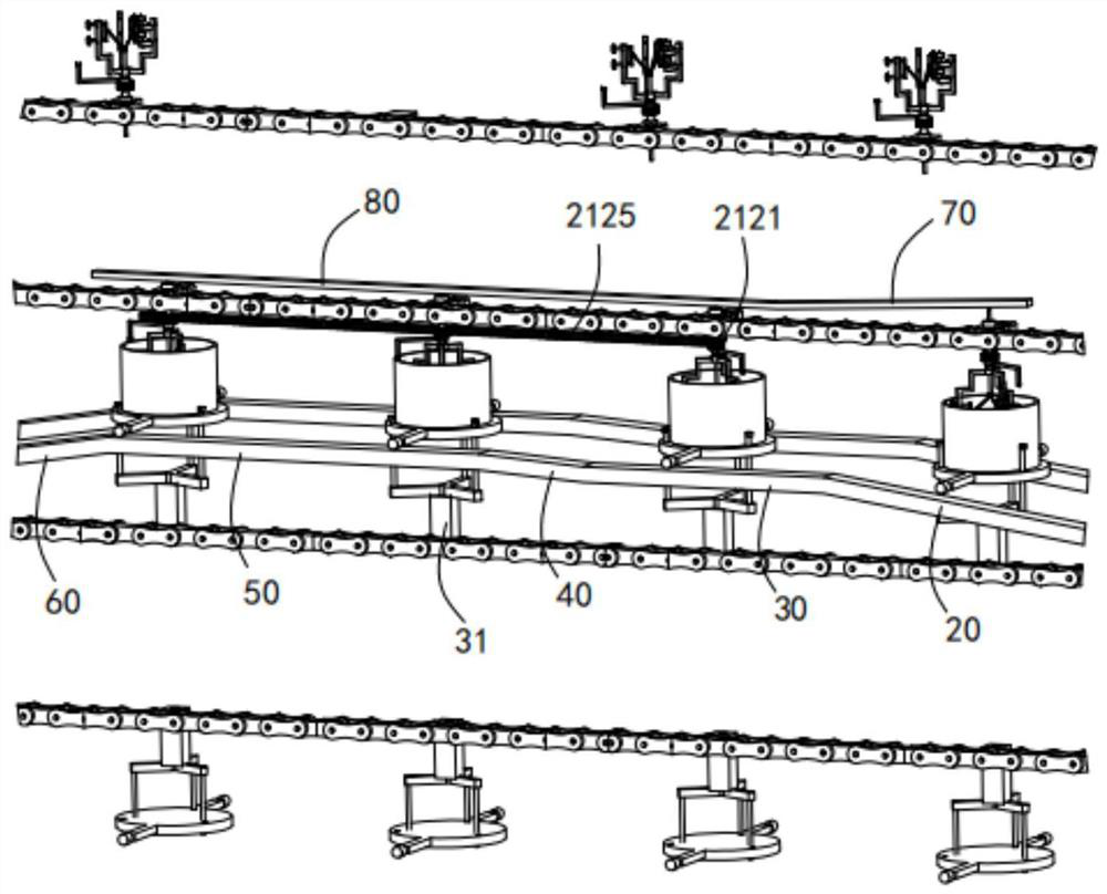
[0052] Such as Figure 6 and Figure 8 As shown, the parts that are the same as or corresponding to those in Embodiment 1 adopt the reference numerals corresponding to Embodiment 1. For the sake of simplicity, only the differences between Embodiment 1 and Embodiment 1 are described below; the differences between Embodiment 2 and Embodiment 1 The difference is that: the side of the fixed seat a22 is fixedly connected with a guide limit block 6, and a guide limit bar 7 fixed on the frame 1 is arranged above the trimming channel 100, and the guide limit bar 7 The side of 7 is provided with a guide limit groove 71, and the guide limit block 6 slides along the guide limit groove 71.

[0053] In this embodiment, by setting the guide limit block 6 to slide along the guide limit groove 71, the stability of the trimming mechanism is ensured during the clamping and rotating trimming process, and the trimming mechanism is prevented from being tilted and affecting the trimming quality. ...


PUM


Abstract

The invention relates to automatic positioning and trimming equipment. The automatic positioning and trimming equipment comprises a frame, a first rotating chain and a second rotating chain, wherein the first rotating chain and the second rotating chain are arranged on the frame; the first rotating chain and the second rotating chain are arranged from the top to the bottom; a plurality of trimmingmechanisms are arranged on the first rotating chain; a plurality of support mechanisms are arranged on the second rotating chain in an array manner; a trimming channel is formed between the first rotating chain and the second rotating chain; the trimming mechanisms are in top-to-bottom one-to-one correspondence with the trimming mechanisms which are transmitted to pass through the trimming channel under driving of the second rotating chain when the trimming mechanisms are transmitted to pass through the trimming channel under the driving of the first rotating chain, and the trimming mechanisms and the support mechanism are kept static relative to each other; the support mechanisms are used for bearing plastic parts; and the trimming mechanisms are matched with the support mechanisms for supporting and fixing the plastic parts which are transmitted to pass through the trimming channel and rotatably trimming upper end openings of the plastic parts in the transmission process. Through the automatic positioning and trimming equipment, the problems of low plastic part end opening trimming efficiency, low trimming quality, serious plastic part end opening tool marks and high consumptionof manpower of the existing equipment are solved.

Description

Technical field: [0001] The invention belongs to the technical field of plastic parts production, and more specifically relates to an automatic positioning trimming device. Background technique: [0002] Plastic parts generally need to be deburred. For example, at the port position, the burrs need to be trimmed manually, which is inefficient. Some simple trimming devices are inconvenient to operate and low in efficiency, especially when dealing with cylindrical plastic parts. The trimming of the port is not only inefficient, but also has serious knife marks. [0003] A Chinese utility model patent with the publication number CN209615594U discloses a battery box automatic trimming detection equipment, and specifically discloses that multiple battery boxes are positioned and fixed at the same time by setting a positioning mechanism and a supporting transfer mechanism a, and then Through the lateral movement of the cutting knife of the provided cutting knife mechanism, the upp...

Claims


Application Information

Patent Timeline
Patent Type & Authority Applications(China)
IPC IPC(8): B29C37/02B29L31/00
CPCB29C37/02B29L2031/7146
Inventor 周炜
Owner 周炜
Why Eureka
Try Eureka