Water surface floating object collecting device

A technology for collecting floating objects on the water surface, which is applied to the cleaning of open water surfaces, water conservancy projects, construction, etc., can solve the problems of inconvenient collection of floating objects on the water surface, and achieve the effects of high work efficiency, simple collection work, and fast collection

Pending Publication Date: 2020-09-04
BOYA GONGDAO BEIJING ROBOT TECH CO LTD
View PDF0 Cites 3 Cited by
  • Summary
  • Abstract
  • Description
  • Claims
  • Application Information

AI Technical Summary

Problems solved by technology

[0005] The object of the present invention is to provide a device for collecting floating objects on the water surface to solve the technical problem of inconvenient collection of floating objects on the water surface existing in the prior art

Method used


Image

  • Water surface floating object collecting device
  • Water surface floating object collecting device
  • Water surface floating object collecting device

Examples


Embodiment 1

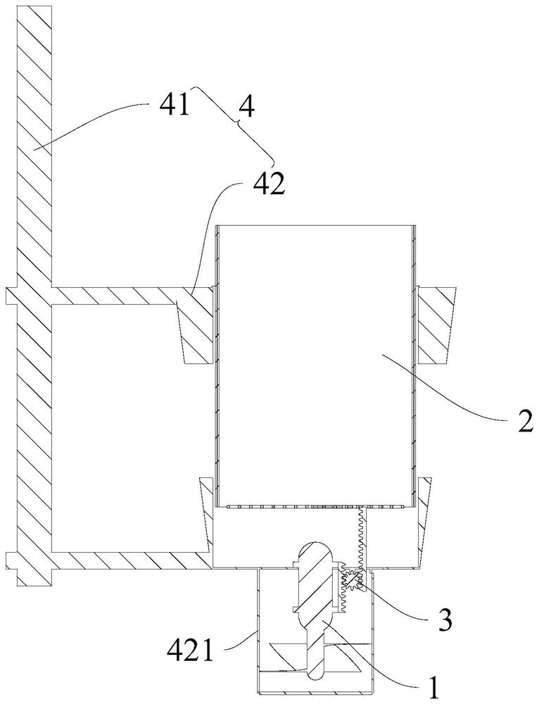
[0059] Such as Figure 1-4 As shown, the present invention provides a water surface floating object collection device, which includes a drainage mechanism 1, a collection bucket 2, a movement mechanism 3, and a fixing mechanism 4. The fixing mechanism 4 includes a fixed bracket 41 and is fixed on one side of the fixed bracket 41 The support assembly 42 includes two ring structures sleeved on the outside of the collection bucket 2, wherein the ring structure at the lower end is also fixed with a movement mechanism 3, and the drainage mechanism 1 is located below the movement mechanism 3 and passes through the movement mechanism 3 is connected to the collection bucket 2, such as figure 1 Shown.

[0060] When the drainage mechanism 1 is activated and the water above it is discharged downward, the drainage mechanism 1 moves upward by the reaction force of the water and drives the movement mechanism 3 to start working. The structure of the movement mechanism 3 is as follows Figure 4 S...

Embodiment 2

[0063] Such as Figure 5 As shown, the difference between this embodiment 2 and embodiment 1 is that the support assembly 42 in the water surface float collection device is a hollow columnar structure. When the drainage mechanism 1 is activated, the drainage mechanism 1 can only be located in the support assembly 42 And the water in the collection bucket 2 is discharged downwards, and the water in the surrounding environment will not be sucked. Therefore, compared with Embodiment 1, the working efficiency of the device can be greatly improved.

Embodiment 3

[0065] Such as Figure 6-7 As shown, the difference between the third embodiment and the second embodiment is that the structure of the movement mechanism 3 in the water surface floating object collection device is changed, which is caused by Figure 5 The rack and pinion meshing structure in Figure 7 The fixed pulley structure shown.

[0066] Specifically, the movement mechanism 3 includes a pulley 34 and a connecting belt 35 connected to the pulley 34. The pulley 34 is fixedly arranged on the support assembly 42. Both ends of the connecting belt 35 extend in the same direction and are respectively connected to the collection bucket 2 and the drainage mechanism 1. Connected.

[0067] It should be noted that the axis of the pulley 34 is always below the two ends of the connecting belt 35.

[0068] When the drainage mechanism 1 is activated, the drainage mechanism 1 itself will move upward under the action of the reaction force. At this time, the position of the pulley 34 is fixed a...


PUM


Abstract

The invention provides a water surface floating object collecting device, and relates to the technical field of water body treatment. The water surface floating object collecting device is mainly usedfor solving the technical problem that in the prior art, the collection of water surface floating objects is inconvenient. The water surface floating object collecting device comprises a drainage mechanism and a collecting barrel. The upper end of the collecting barrel is located above the liquid level, and a filtering screen is arranged at the lower end of the collecting barrel. The drainage mechanism is located below the liquid level, and when the drainage mechanism is started, the liquid which is located in the collecting barrel can be downwards drained. The drainage mechanism and the collecting barrel are connected with each other through a movement mechanism. When the drainage mechanism is started and downwards drains water, the drainage mechanism can upwards move due to the counteracting force, the movement mechanism works under the action of the drainage mechanism and pulls the collecting barrel to downwards move to the space located below the water surface at this moment, andthe water surface floating objects can flow into the collecting barrel along with the water flow at this moment. The water surface floating object collecting device is used for water body environmenttreatment and can conveniently achieve the collection of water surface floating type garbage.

Description

Technical field [0001] The invention relates to the technical field of water body treatment, in particular to one. Background technique [0002] With the development of economy and society, all kinds of disposable products, plastic products, etc. are flooding our lives. The sea, lakes, rivers, reservoirs and other water bodies are all polluted by plastic garbage to varying degrees, especially floating garbage, which will not only destroy aquatic life. The growth environment of organisms affects the beauty of water bodies and also seriously affects the normal navigation of ships. [0003] At present, there are two ways to solve floating garbage: manual salvage and fixed garbage collection. Manual salvage needs to be handled with a net bag, which is not only cumbersome and inefficient, but also has problems such as low operational safety and environmental constraints. Fixed trash can collection can greatly reduce the dependence on manpower for salvage operations, but fixed trash ca...

Claims


Application Information

Patent Timeline
Patent Type & Authority Applications(China)
IPC IPC(8): E02B15/10
CPCE02B15/10
Inventor 熊明磊陈龙冬王老虎
Owner BOYA GONGDAO BEIJING ROBOT TECH CO LTD
Why Eureka
Try Eureka