Rotary atomizer applied to new energy electrode material drying

A technology of rotary atomizer and electrode material, which is applied in the directions of drying solid materials, drying gas arrangement, heating to dry solid materials, etc., can solve the problems of inconvenient cables, traction connections, and complicated wiring assembly of the body, so as to improve the fixed the effect of strength

Active Publication Date: 2022-07-08
无锡沃得旋转雾化科技有限公司
View PDF27 Cites 0 Cited by
  • Summary
  • Abstract
  • Description
  • Claims
  • Application Information

AI Technical Summary

Problems solved by technology

[0005] The purpose of the present invention is to solve the complicated circuit assembly of the traditional rotary atomizer in the prior art. When assembling the rotary atomizer, it is not necessary to The shortcomings of the convenience of pulling and connecting the cables of the rotary atomizer, and a rotary atomizer applied to the drying of new energy electrode materials

Method used


Image

  • Rotary atomizer applied to new energy electrode material drying
  • Rotary atomizer applied to new energy electrode material drying
  • Rotary atomizer applied to new energy electrode material drying

Examples


Embodiment 1

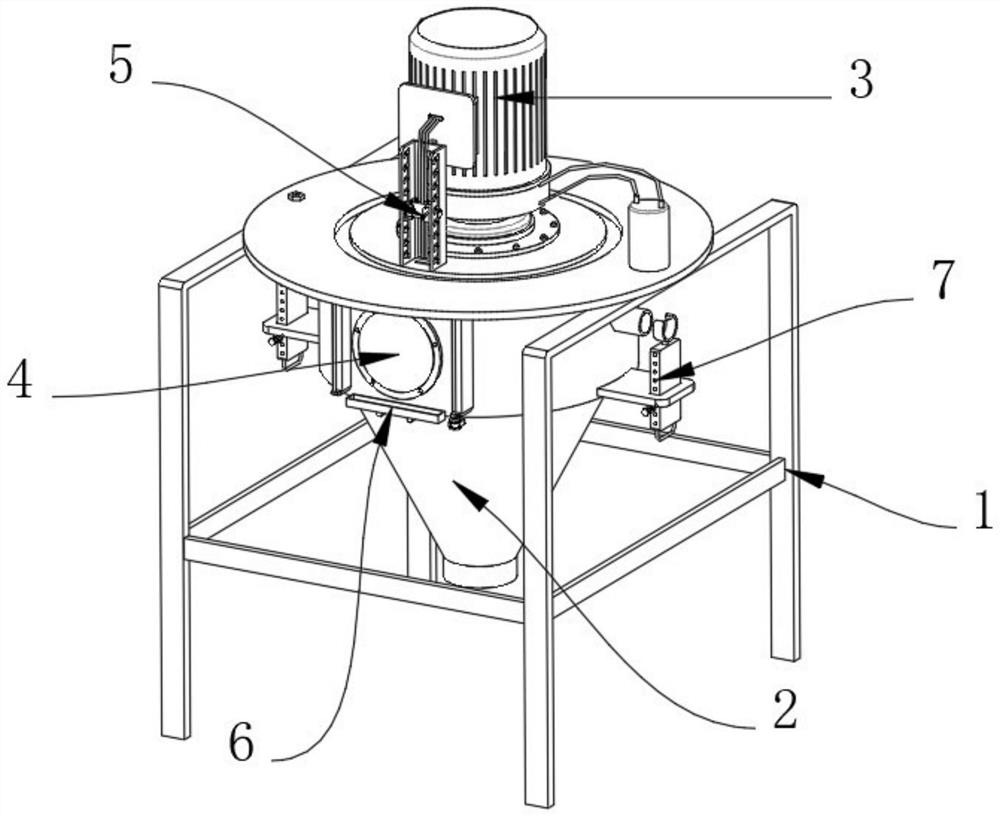
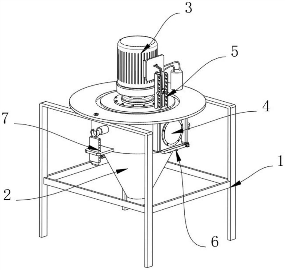
[0048] Example 1, as Figure 1-8 As shown, the present invention provides a rotary atomizer applied to the drying of new energy electrode materials, including a bracket 1 and a lead structure 5, a barrel 2 is installed on the surface of the bracket 1, and an atomizer is installed inside the barrel 2, The circular arc surface of the barrel 2 is provided with an observation mirror 4 by means of bolts, the upper end of the barrel 2 is provided with a servo motor 3, the upper end of the barrel 2 is provided with a lead structure 5, and the circular arc surface of the barrel 2 is provided with a cleaning structure 6, The arc surface of the barrel 2 is provided with a support structure 7 .

[0049] The specific settings and functions of the lead structure 5 , the cleaning structure 6 and the support structure 7 will be described in detail below.

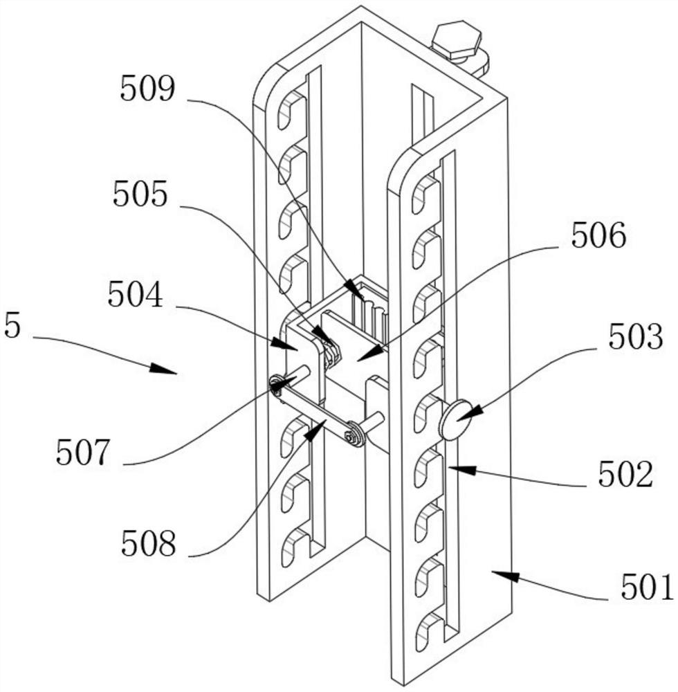
[0050] like image 3 and Figure 4 as well as Figure 9 and Figure 10 As shown, the lead structure 5 includes an extension frame 50...

Embodiment 2

[0057] Embodiment 2, on the basis of Embodiment 1, the support structure 7 includes a welding plate 71, the welding plate 71 is fixedly connected to the arc surface of the barrel 2, and a support plate 72 is slidably inserted in the welding plate 71. The support plate 72 A handle 78 is fixedly connected to the lower end of the support plate 72, a bracket 76 is fixedly connected to the upper end of the support plate 72, an elastic rope 77 is fixedly connected to the inner side of the bracket 76, a number of card holes 75 are evenly opened on one side of the support plate 72, and the welding plate 71 A connecting block 73 is fixedly connected to the lower surface of the connecting block 73, and a plug 74 is slidably inserted in the connecting block 73. The size of the plug 74 is adapted to the size of the card hole 75 of the support plate 72, so that the feeding pipe and the water inlet pipe are connected to the When the barrel 2 is on, the feeding pipe or the water inlet pipe ca...


PUM


Abstract

The invention provides a rotary atomizer applied to new energy electrode material drying, and relates to the technical field of rotary atomizers, the rotary atomizer comprises a support and a lead structure, a material barrel is installed on the surface of the support, an atomizer is installed in the material barrel, and an observation mirror is installed on the arc surface of the material barrel through bolts; a servo motor is installed at the upper end of the charging barrel, a lead structure is arranged at the upper end of the charging barrel and comprises an extension frame, the extension frame communicates with the upper end of the charging barrel, limiting holes are formed in the two sides of the extension frame and are rectangular, and sliding rods are slidably connected to the inner walls of the rectangular limiting holes in the extension frame. The ends, close to each other, of the two sliding rods are fixedly connected with a sliding frame, and the section of the sliding frame is in a U shape. According to the rotary atomizer, the problems that machine body circuit assembly of a traditional rotary atomizer is complex, and when the rotary atomizer is assembled, traction connection of a cable of the rotary atomizer is inconvenient are solved.

Description

technical field [0001] The invention relates to the technical field of rotary atomizers, in particular to a rotary atomizer used for drying new energy electrode materials. Background technique [0002] The rotary atomizer is suitable for drying solutions, emulsions, suspensions, etc. to form powders. The air is filtered and heated, and enters the air distributor at the top of the dryer. Dry treatment. [0003] In the process of processing new energy batteries, the electrodes are often dried and then shaped. Lithium iron phosphate, as the main material of new energy electrodes, will generate excess debris during processing. In order to facilitate the recycling of these excess debris, it is often necessary to It is dried with a rotary atomizer. [0004] The body circuit assembly of the traditional rotary atomizer is relatively complicated. When assembling the rotary atomizer, it is inconvenient to pull and connect the cables of the rotary atomizer, and the proficiency of the...

Claims


Application Information

Patent Timeline
Patent Type & Authority Applications(China)
IPC IPC(8): F26B3/10F26B5/08F26B21/00F26B17/10F26B25/00
CPCF26B3/10F26B5/08F26B21/004F26B17/10F26B25/002Y02E60/10
Inventor 蒋春牛诸林峰章敏卫
Owner 无锡沃得旋转雾化科技有限公司
Why Eureka
Try Eureka