
Eureka
For R&D, Eureka makes reading and utilizing patents & technical documents easy.
Eureka AIR
Designed for self-driven R&D workflows. Generate viable solutions, solve complex R&D challenges, empower your innovation with AI.

Eureka Materials
Designed for material experts only. Revolutionize your material R&D, from search, analyze, to developing new materials.

TechResearch
Generate reliable direction feasibility study reports for your R&D in just a few steps.

TechSeek
Discover and master advanced knowledge NOW. Basics, ideas, possibilities, all at once.

TechMind
As an expert in R&D Theories, TechMind can generates customized viable solutions instantly.

TechRisk
Analyze your overall solution with one click, know your potential R&D risks in advance.

TechMonitor
Get weekly tech updates, stay abreast of the latest tech innovations and key insights.
Ceramic tile surface cement applying device
A technology for cement and ceramic tiles, which is applied in the direction of construction and building structure, can solve the problems of time-consuming and laborious cement application work, and inability to apply cement on the surface of ceramic tiles, so as to achieve the effect of being easy to take out and use.
- Summary
- Abstract
- Description
- Claims
- Application Information
AI Technical Summary
Problems solved by technology
Method used
Image

Examples
Embodiment 1
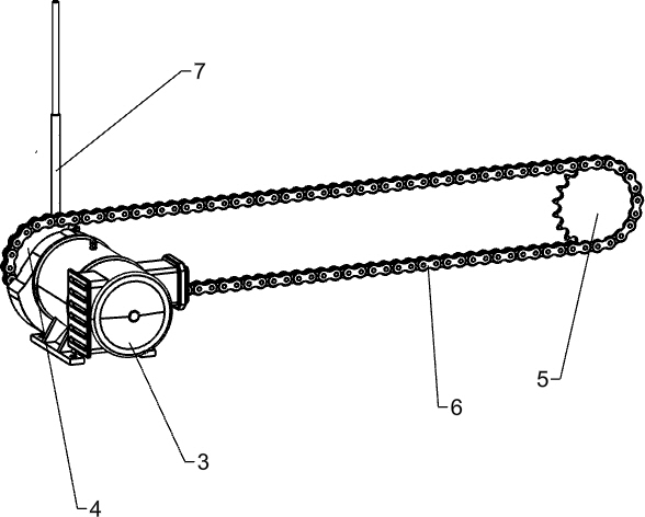
[0021] A kind of ceramic tile surface cement applicator, as Figure 1-4 As shown, it includes a frame 1, a placement plate 2, a power assembly and a blanking assembly. The front and rear sides of the top of the frame 1 are welded with a placement plate 2, and the front side of the top of the frame 1 is provided with a power assembly powered by a motor. The sliding type on the top of the plate 2 is provided with a blanking assembly for blanking by moving.
[0022] like figure 1 and 2 As shown, the power assembly includes a reduction motor 3, a first sprocket 4, a second sprocket 5, a chain 6 and a telescopic rod 7, and the left side of the top front side of the frame 1 is fixed with a reduction motor 3 by bolts, and the reduction motor 3 The output shaft is connected with the first sprocket 4 by the rotating rod, the frame 1 is provided with the second sprocket 5 in the front right rotation mode, and the chain 6 is installed between the first sprocket 4 and the second sprocke...
Embodiment 2
[0028] like figure 1 and 5 Shown, also comprise second bracing frame 12, guide post 13, storage box 14, baffle plate 15, push plate 16 and spring 17, frame 1 top left rear part is welded with second bracing frame 12, the second Guide pillars 13 are installed on the front and rear sides of the upper part of the left side of the support frame 12. A material storage box 14 is provided by bolts between the second support frame 12 tops. The left side is welded with a push plate 16, and the push plate 16 is slidably installed on the guide posts 13 on both sides, and the spring 17 is connected between the left side of the push plate 16 and the guide post 13 left parts.
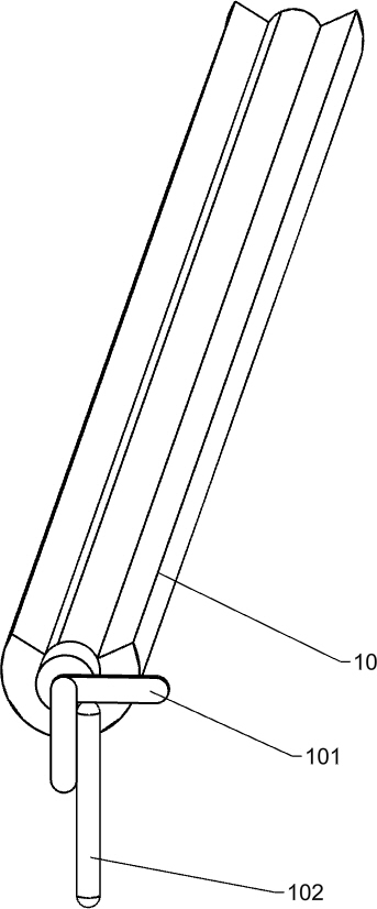
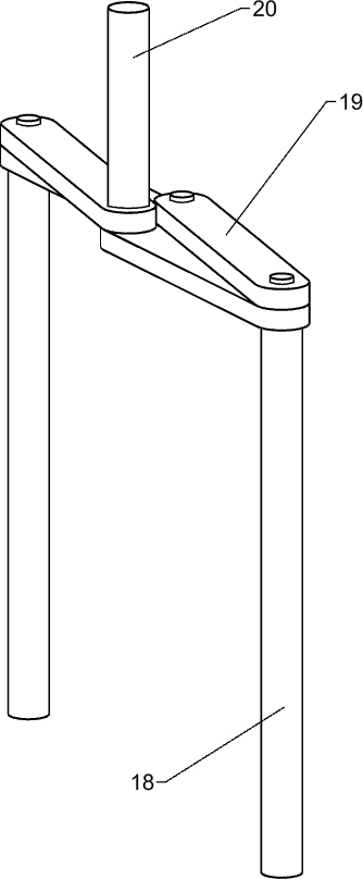
[0029] like figure 1 and 6 Shown, also comprise support bar 18, telescopic frame 19 and the second stop bar 20, frame 1 left side front and back symmetrical sliding type is provided with support bar 18, and support bar 18 top rotation type is provided with telescopic frame 19, and telescopic frame 19 A second blo...
PUM
 Abstract
Description
Claims
Application Information
 - R&D Engineer
- R&D Manager
- IP Professional
- Industry Leading Data Capabilities
- Powerful AI technology
- Patent DNA Extraction
Browse by: Latest US Patents, China's latest patents, Technical Efficacy Thesaurus, Application Domain, Technology Topic, Popular Technical Reports.
© 2024 PatSnap. All rights reserved.Legal|Privacy policy|Modern Slavery Act Transparency Statement|Sitemap|About US| Contact US: help@patsnap.com