High-efficiency low-energy-consumption clear water self-priming pump

A self-priming pump, low energy consumption technology, applied to the components, pumps, drive pumps, etc. of the pumping device for elastic fluid, can solve the problems of small contact area and low pumping efficiency, and achieve increased contact area and improved safety. resistance, overcoming the effect of small contact area

Active Publication Date: 2020-09-04
ESKE PUMP
View PDF6 Cites 0 Cited by
  • Summary
  • Abstract
  • Description
  • Claims
  • Application Information

AI Technical Summary

Problems solved by technology

[0005] In one aspect disclosed in the embodiments of the present invention, the self-priming pump body and the motor are stored in the storage box through the use of the first storage board, the second storage board, the third storage board and the fourth storage board. In the box, the stability and safety of the self-priming pump body can be improved by storing the box body, and the contact area of ​​the self-priming pump body can be increased by storing the box body, making the self-priming pump body work more stable, and can The box can isolate and protect the self-priming pump body to prevent non-staff or animals from getting close to the self-priming pump body, which will affect the work of the self-priming pump body. Through several storage holes, the working conditions of the self-priming pump body can be observed, and It can play the role of protection and heat dissipation, improves the safety of the self-priming pump body, and overcomes the shortcomings of the existing scheme that the self-priming pump body has a small contact area with the ground and is easily affected by the external environment, resulting in low pumping efficiency;

Method used


Image

  • High-efficiency low-energy-consumption clear water self-priming pump
  • High-efficiency low-energy-consumption clear water self-priming pump
  • High-efficiency low-energy-consumption clear water self-priming pump

Examples


Embodiment Construction

[0034] The technical solutions of the present invention will be clearly and completely described below in conjunction with the embodiments. Apparently, the described embodiments are only some of the embodiments of the present invention, not all of them. Based on the embodiments of the present invention, all other embodiments obtained by persons of ordinary skill in the art without creative efforts fall within the protection scope of the present invention.

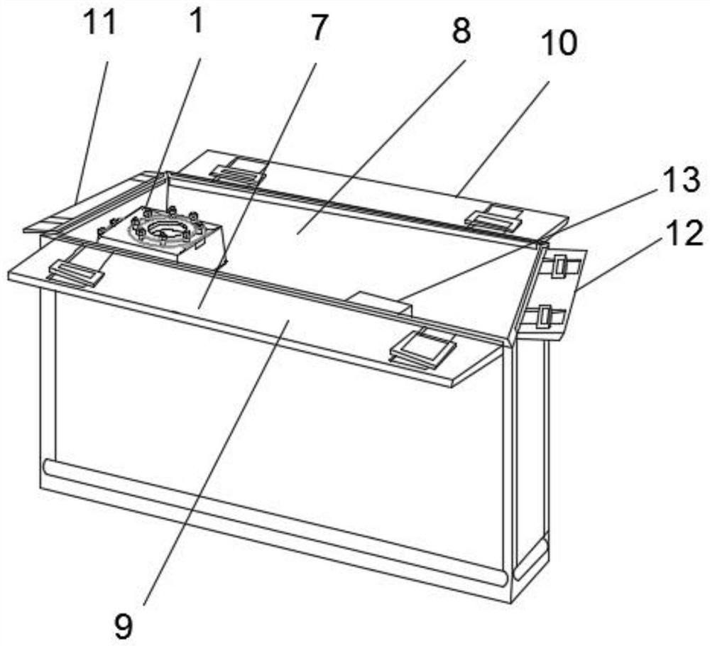
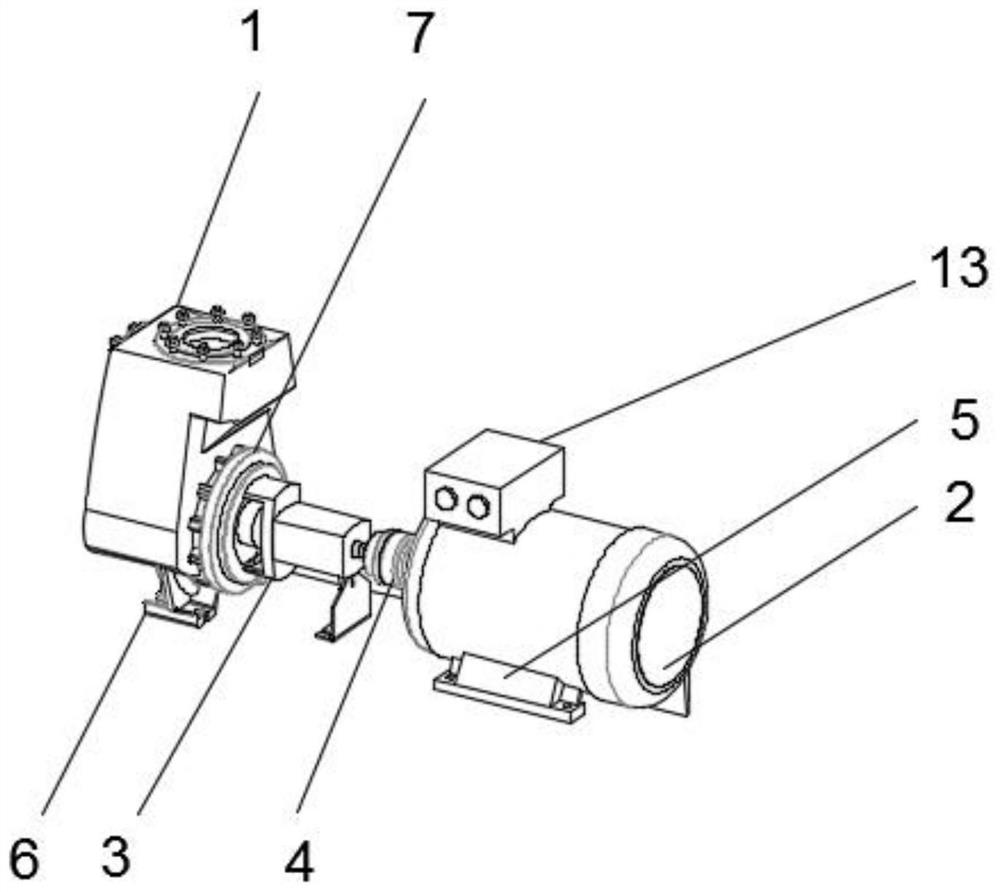
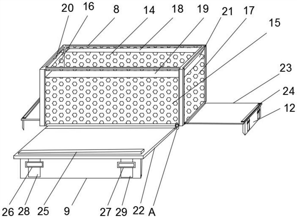
[0035] like Figure 1-6 As shown, a clean water self-priming pump with high efficiency and low energy consumption comprises a self-priming pump body 1 and a storage box 8, the self-priming pump body 1 is located inside the storage box 8, and the self-priming pump body 1 A motor 2 is fixedly connected to one side, and a bearing body 3, a shaft column 4 and a sealing flange 7 are fixedly connected between the self-priming pump body 1 and the motor 2, and the bearing body 3 is located between the sealing flange 7 and the shaft...


PUM


Abstract

The invention discloses a high-efficiency low-energy-consumption clear water self-priming pump. By means of a containing box body, the contact area of a self-priming pump body can be increased, so that stability achieved when the self-priming pump body works is better; and in addition, the self-priming pump body can be isolated and protected, and non-staff or animals are prevented from approachingthe self-priming pump body. By means of multiple containing holes, the working condition of the self-priming pump body can be observed; in addition, the protection and heat dissipation effects can beachieved; safety of the self-priming pump body is improved; and the defects that in the existing scheme, when the self-priming pump body pumps water, the contact area of the self-priming pump body and the ground is small, and the self-priming pump body can be affected by the external environment easily, so that the water pumping efficiency is low are overcome. Non-slip mats at the lower ends of afirst fixing plate, a second fixing plate, a third fixing plate and a fourth fixing plate are in contact with the ground; and multiple first balancing weights and second balancing weights move downwards to the upper ends of the non-slip mats for increasing the weight, so that the problem that in the existing scheme, the self-priming pump body is not good in fixing stability is solved.

Description

technical field [0001] The invention relates to the technical field of self-priming pumps, in particular to a clean water self-priming pump with high efficiency and low energy consumption. Background technique [0002] The self-priming pump is a self-priming centrifugal pump. It has the advantages of compact structure, convenient operation, stable operation, easy maintenance, high efficiency, long life, and strong self-priming ability. Before starting, it is only necessary to ensure that there is a quantitative suction liquid stored in the self-priming pump body. Different liquids can use self-priming pumps of different materials. The working principle of the self-priming pump is to fill the pump casing with water before starting the pump. The rotation makes the water in the impeller channel flow to the volute, at this time the inlet forms a vacuum, the water inlet check door opens, the air in the suction pipe enters the pump, and reaches the outer edge through the impeller ...

Claims


Application Information

Patent Timeline
Patent Type & Authority Applications(China)
IPC IPC(8): F04D9/02F04D29/00F04D29/62
CPCF04D9/02F04D29/007F04D29/628
Inventor 孙才军曹珠明曲昌平
Owner ESKE PUMP
Why Eureka
Try Eureka