Field operation optical cable splice closure and using method thereof

A field optical cable and splice box technology, applied in the directions of light guides, optics, optical components, etc., can solve the problems of high use cost, low splice efficiency, inconvenient operation, etc., and achieve the effect of reduced splice cost, simple structure and convenient splice.

Pending Publication Date: 2020-09-04
四川微云智联科技有限公司
View PDF1 Cites 1 Cited by
  • Summary
  • Abstract
  • Description
  • Claims
  • Application Information

AI Technical Summary

Problems solved by technology

[0010] The object of the present invention is to overcome the disadvantages of inconvenient operation, low splicing efficiency and high use cost of the optical cable splicing box in the prior art when connecting optical cables, and provide a field optical cable splicing box. The optical cable splicing box has simple structure, convenient The advantages of operation, the use method can quickly complete the splicing of optical cables, the field optical cable splicing box and its use method described in the present invention can effectively improve the efficiency of optical cable splicing

Method used


Image

  • Field operation optical cable splice closure and using method thereof
  • Field operation optical cable splice closure and using method thereof

Examples


Embodiment 1

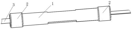
[0051] This embodiment includes a housing 1 and a fixing fixture 4. Both ends of the housing 1 are connected with terminals 2. After the optical cable 3 is connected, the fixing fixture 4 is clamped at the joint of the optical cable 3, and the joint of the optical cable 3 is sealed in the housing. In body 1.

[0052] Further optimization, after the terminal 2 is connected to the housing 1, the housing 1 and the terminal 2 form a cavity, and the cavity is filled with sealing glue.

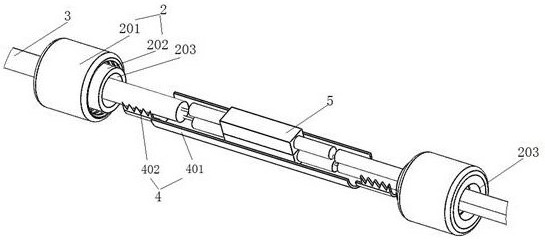
[0053] Further optimization, the fixing fixture 4 includes a connecting part 401, and the clamping part at both ends of the connecting part 401 is a serrated connecting part 402, the serrated connecting part 402 can clamp the optical cable 3, and the serrated connecting part 402 can be embedded in the sheath of the optical cable 3 .

[0054] Among them, in order to better ensure that the connection of the optical cable 3 has better tensile properties, a protrusion is provided on the side facing the...

Embodiment 2

[0064] This embodiment is basically the same as Embodiment 1, the difference is that: the housing 1 is cylindrical, the diameter of the housing 1 is 14 mm, and the length is 105 mm.

Embodiment 3

[0066] This embodiment is basically the same as Embodiment 1, the difference is that: the housing 1 is cylindrical, the diameter of the housing 1 is 16 mm, and the length is 110 mm.

[0067] In actual use, the specific usage method of the field optical cable splice box is as follows:

[0068] S1: Pass one of the optical cables 3 through the wire hole 203 on one of the ends 2, and make the sheath of the optical cable 3 and the wire hole 203 on the elastic member 202 in the end 2 achieve an interference fit;

[0069] S2: Pass another optical cable 3 through the wire hole 203 on the other end 2, and make the sheath of the optical cable 3 and the wire hole 203 on the elastic member 202 in the end 2 achieve an interference fit;

[0070] S3: passing the optical cable 3 described in S1 or S2 through the housing 1, so that the housing 1 is placed on the optical cable 3;

[0071] S4: After connecting two optical cables 3, place the joint of the optical cable 3 in the connection part 4...


PUM

PropertyMeasurementUnit
diameteraaaaaaaaaa
lengthaaaaaaaaaa
diameteraaaaaaaaaa

Abstract

The invention discloses a field operation optical cable splice closure and a using method thereof. The field operation optical cable splice closure comprises a housing and a fixing clamp. The two endsof the housing are connected with ends; after an optical cable is spliced, the fixing clamp is clamped at the splicing position of the optical cable; and the splicing position of the optical cable islocated in the housing. The use method comprises the following steps: S1, enabling one optical cable to pass through a wire hole in one end, and enabling the sheath of the optical cable to be in interference fit with the wire hole; S2, enabling the other optical cable to pass through a wire hole in the other end, and enabling the sheath of the optical cable to be in interference fit with the wirehole; S3, enabling the optical cable in the step S1 or the step S2 to pass through the housing, and enabling the housing to sleeve the optical cable; and S4, connecting the two optical cables, placing the connecting positions of the optical cables in the connecting part of the fixing clamp, and clamping the sawtooth-shaped connecting pieces at the connecting positions. The optical cable splice closure has the advantages of being simple in structure and convenient to operate, and the optical cables can be quickly connected by using the using method provided in the invention.

Description

technical field [0001] The invention relates to an optical cable connection device, in particular to a field optical cable connection box and a method for using the same. Background technique [0002] Military field optical cable is a metal-free optical cable specially designed for rapid wiring or repeated retractable use in field operations and complex environments. It is light in weight and easy to carry; it has high tensile strength, pressure resistance, and high strength-to-weight ratio; good flexibility , easy to bend; oil-resistant, wear-resistant, flame-retardant; applicable to a wide temperature range and so on. It is suitable for rapid wiring or repeated retraction of military field communication systems; radar, aviation and ship wiring; oil fields, mines, ports, live TV broadcasts, emergency repairs of communication lines and other harsh conditions. [0003] The military field optical cable is generally a roll of about 1 km, and each roll is connected through a sp...

Claims


Application Information

Patent Timeline
Patent Type & Authority Applications(China)
IPC IPC(8): G02B6/44
CPCG02B6/4446G02B6/4454G02B6/4479G02B6/501G02B6/44384
Inventor 王智荣阳杰马烈勇
Owner 四川微云智联科技有限公司
Why Eureka
Try Eureka