Method for accurately detecting fault information of IT equipment in machine room

A technology for equipment failure and detection methods, applied in computer parts, instruments, characters and pattern recognition, etc., can solve the problems of lack of risk warning, poor flexibility, less inspection, missed inspection or false inspection, etc., to improve the efficiency of inspection , the effect of reducing risks and reducing labor costs

Active Publication Date: 2020-09-04
杭州优云科技有限公司
View PDF2 Cites 14 Cited by
  • Summary
  • Abstract
  • Description
  • Claims
  • Application Information

AI Technical Summary

Problems solved by technology

The working method of manual inspection not only consumes a lot of labor costs, but also cannot guarantee the authenticity of the inspection data, which is prone to under-inspection, missed inspection or false detection; in addition, when a fault occurs, it is easy to cause the failure alarm to be delayed , there is a lack of risk warning, and it is impossible to judge the fault information initially, and the query and communication efficiency of inspection information under multi-party supervision is low
Although there is currently an inspection robot that compares the fault information of the indicator light with the traditional image of the normal state, this method is less flexible, requires high positioning accuracy, and is not intelligent enough

Method used


Image

  • Method for accurately detecting fault information of IT equipment in machine room
  • Method for accurately detecting fault information of IT equipment in machine room
  • Method for accurately detecting fault information of IT equipment in machine room

Examples


Embodiment Construction

[0055] In order to facilitate those skilled in the art to better understand the present invention, the present invention will be further described in detail below in conjunction with the accompanying drawings and specific embodiments. The following are only exemplary and do not limit the protection scope of the present invention.

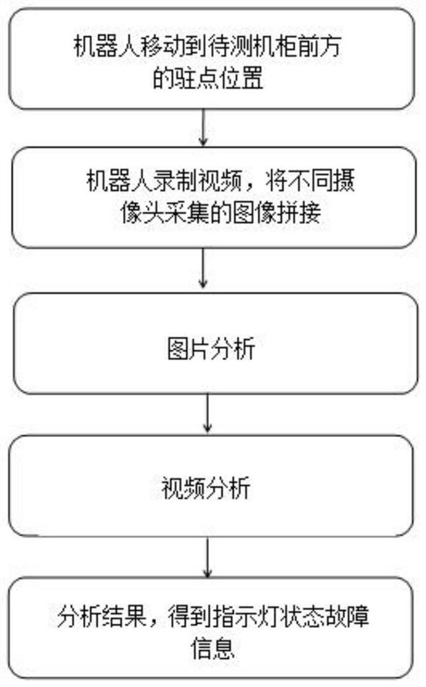
[0056] Such as figure 2 As shown, the method for accurately detecting fault information of IT equipment in a computer room according to this embodiment includes the following:

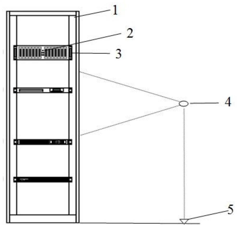
[0057] S1. The robot moves to the calibrated stagnation position in front of the cabinet to be tested.

[0058] In this embodiment, as figure 1 As shown, 1 indicates the cabinet to be tested, 2 indicates the indicator light, 3 indicates the IT equipment, 4 indicates the camera on the robot, 5 indicates the stagnation position, and at least one row of cameras is installed on the robot ( figure 1 Only one is identified). There are several cameras in each column at equal intervals fr...


PUM


Abstract

The invention discloses a method for accurately detecting fault information of IT equipment in a machine room. The method comprises the steps that S1, a robot moves to a calibrated stationary point position in front of a to-be-detected cabinet; s2, a plurality of cameras on the robot record videos of the to-be-tested cabinet, and first frame images of the videos recorded by different cameras are spliced into an image covering the whole to-be-tested cabinet up and down; s3, picture analysis is carried out; s4, video analysis is carried out; and S5, picture analysis and video analysis results are integrated to obtain indicating lamp state fault information. According to the invention, the state information of the static indicator lamp and the flashing lamp of the IT equipment is analyzed bycombining a deep learning image technical means; the equipment and the fault indicator lamp of the equipment can be detected in time, the information of the equipment and the fault indicator lamp of the equipment can be accurately alarmed, solutions can be pre-judged, workers only need to finally check the inspection report, an innovative technical detection means is provided for data management of the unattended machine room, and the machine room inspection problems of low inspection efficiency, incomplete recording, less inspection, false inspection and the like are effectively solved.

Description

Technical field [0001] The invention relates to the technical field of intelligent patrol inspection of a computer room, in particular to a method for accurately detecting fault information of IT equipment in a computer room. Background technique [0002] With the rapid development of the information society, modern information technology and automation equipment have shown an explosive growth trend, and the scale of data centers has also continued to grow, which requires higher and higher security and stability of data centers. As an important data center, the computer room has become vital to its fault detection and elimination. The hidden dangers of equipment failure in the computer room are mainly caused by the long-time power-on operation of the network equipment, storage equipment, and servers in the computer room, the aging of the equipment, and manual misoperation. If the assets and equipment failures caused by these situations are not reported in time and pointed out th...

Claims


Application Information

Patent Timeline
Patent Type & Authority Applications(China)
IPC IPC(8): G06K9/00G06K9/34G06K9/62
CPCG06V20/10G06V10/267G06F18/22G06F18/214
Inventor 石磊钟芳挺
Owner 杭州优云科技有限公司
Why Eureka
Try Eureka